
Method and apparatus for cooling electronic enclosures

Inactive Publication Date: 2006-05-30
VERTIV CORP
View PDF27 Cites 140 Cited by
  • Summary
  • Abstract
  • Description
  • Claims
  • Application Information

AI Technical Summary

Benefits of technology

[0004]The present invention is an apparatus and method for removing heat generated by the electronics within an enclosure from the room containing such enclosure, thereby reducing or eliminating the heat load from the conventional room air conditioning system. In fact, using the present invention it is possible to supplement the cooling capacity of the room air conditioning system to promote efficient operation.
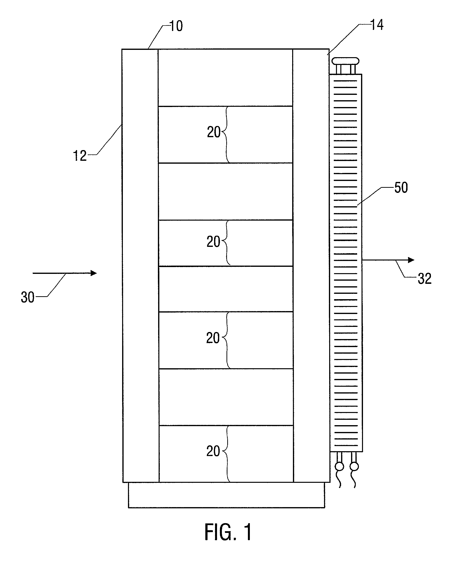
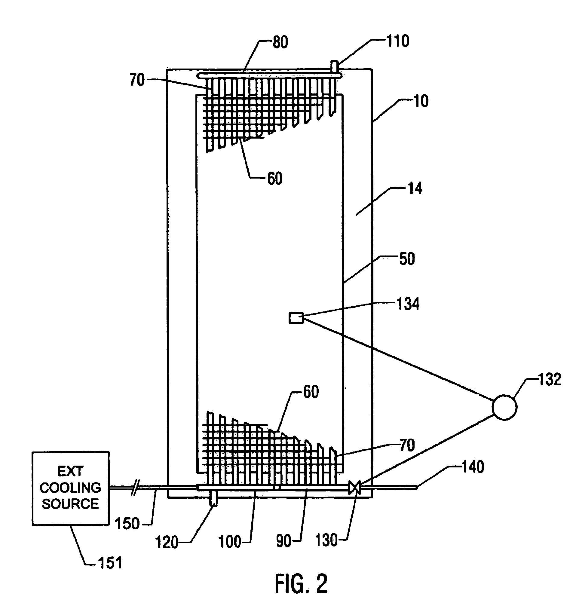
[0005]The principle of operation of the present system is as follows: Air from the computer room at the ambient temperature and humidity is taken into the enclosure and heated by the electronic equipment. The air is then expelled through a heat exchanger, which cools the air back to the ambient temperature. The exiting air is cooled using an external source of chilled water, glycol or a suitable dielectric fluid, which is typically readily available in commercial installations. By returning the air exiting the enclosure to the ambient temperature in the room, the load on the room air conditioning is reduced or eliminated. Furthermore, the cooling fluid provides a more efficient heat transfer medium for removing heat from the room than the room air, as would be the case with a conventional prior art cooling system.

Problems solved by technology

As the density of electronic equipment has increased, it has become increasingly difficult to remove the heat introduced by the electronics from the rooms where such equipment is operated using the conventional room air conditioning alone.

Method used


Image

  • Method and apparatus for cooling electronic enclosures
  • Method and apparatus for cooling electronic enclosures
  • Method and apparatus for cooling electronic enclosures

Examples


Embodiment Construction

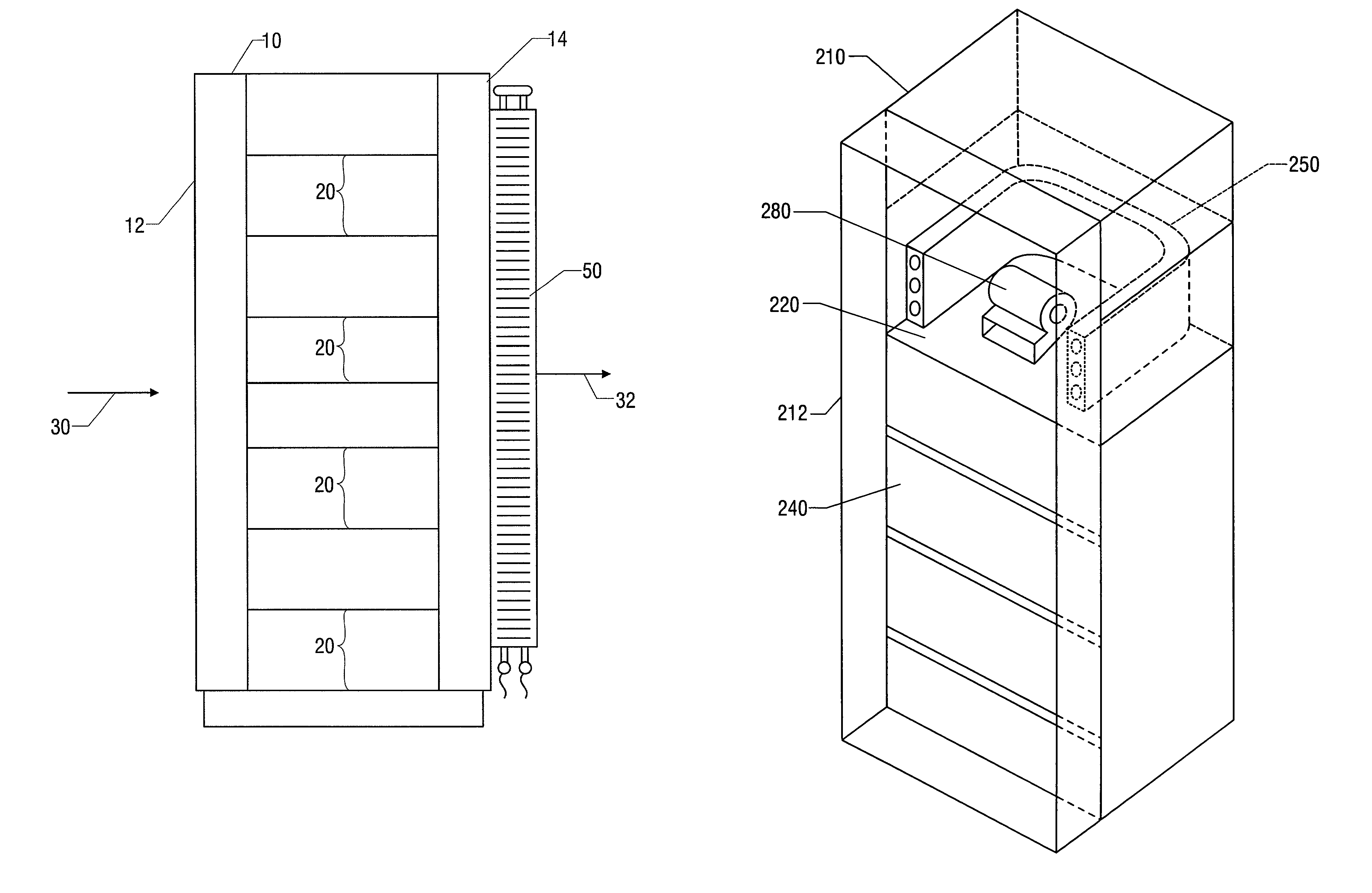
[0021]An apparatus in accordance with the present invention is illustrated in FIG. 1. Electronic equipment, such as computer or telecommunication devices, is housed in a rack enclosure 10. Rack enclosure 10 contains a plurality of equipment mounting racks 20. Mounting racks 20 hold various computer and electronic equipment. Cooling fans integral to the computer equipment draw air 30 from the room, through the front 12 of enclosure 10. The air passes over the electronic equipment mounted in racks 20 and absorbs the heat generated by the electronics. The air 32 flows out the back 14 of enclosure 10 and back into the computer room.

[0022]Because the air used to cool the electronic equipment is returned to the room, the room air conditioning equipment must have adequate capacity to absorb the heat rejected to the room air by the computer equipment. The power dissipation of a typical rack system in use today is approximately 8 kW. However, with the trend of increasingly smaller and faster...


PUM


Abstract

A cooling apparatus and method, and more particularly, an apparatus and method for cooling the air exiting an electronics enclosure, are disclosed. Air is taken into the enclosure and heated by the electronic equipment. The air is then expelled through a heat exchanger, which cools the exiting air. The exiting air is cooled using an external source of cooling liquid, which absorbs the heat from the exiting air. This absorbed heat is then expelled from the liquid outside of the environment containing the enclosure. Cooling the air exiting the enclosure causes the enclosure to present a neutral heat load to a room containing such an enclosure. Cooling the exiting air obviates the necessity of increasing the room air conditioning capacity to account for the heat added to the room by the electronics within the enclosure. Further, the disclosed apparatus and method decrease the possibility of moisture condensation within the enclosure and also provide more efficient cooling than is available from prior art devices and techniques.

Description

CROSS-REFERENCE TO RELATED APPLICATIONS[0001]This application claims the benefit of U.S. Provisional application No. 60 / 190,881, filed Mar. 21, 2000.BACKGROUND OF THE INVENTION[0002]With the expansion of telecommunication and computer technology, increasing amounts of electronic equipment are required at various commercial and business facilities. To facilitate interconnection and access to such equipment, it is typically installed in a common room. Further, technological advancements are permitting more and more electronic equipment to be fit into increasingly smaller spaces. These forces are combining to produce relatively dense electronic installations that generate increasing amounts of heat. For such equipment to operate properly, and to maintain comfort for persons operating and working on such equipment, it is necessary to provide a relatively stable and comfortable temperature and humidity. This has typically been accomplished through the use of air conditioning.[0003]As the...

Claims


Application Information

Patent Timeline
IPC IPC(8): G05D23/00H05K5/00H05K7/20
CPCH05K7/20609H05K7/20736
Inventor BAER, DANIEL B.
Owner VERTIV CORP
Learn More