
Valve operation controller

a valve operation and controller technology, applied in electrical control, non-mechanical valves, machines/engines, etc., can solve the problems of inability to provide optimal valve opening timing, failure of valve operation controller to provide optimal opening/closing timing and lift amount, and inability to realize optimal valve opening/closing timing and other problems, to achieve the effect of eliminating a possible degradation of exhaust gas characteristic and reducing cost and weigh

Inactive Publication Date: 2006-05-30
HONDA MOTOR CO LTD
View PDF18 Cites 15 Cited by
  • Summary
  • Abstract
  • Description
  • Claims
  • Application Information

AI Technical Summary

Benefits of technology

[0011]The present invention has been made to solve the problems mentioned above, and it is an object of the invention to provide a valve operation controller for an internal combustion engine which is capable of optimally setting a valve opening timing and a valve closing timing for an intake valve in accordance with an operating state of the engine to improve the fuel efficiency and power, eliminate fuel stagnation in the intake valve and sticking of the same to its valve seat, and reduce the cost and weight thereof.
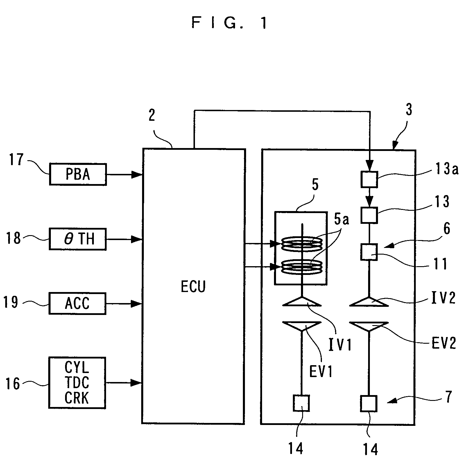
[0014]Thus, the appropriate fuel efficiency and power can be provided in accordance an operating state by combining as appropriate the settings of the opening / closing timings for the first intake valve and the generation and stoppage of the cylinder flowage by the second intake valve in accordance with a particular operating state. For example, in a low rotational speed / low load operating state, a cylinder flowage is generated by the second intake valve to ensure a stable combustion state even with a lean air / fuel mixture, and the opening / closing timings for the first intake valve are set near the combustion fluctuation limit, thereby making it possible to achieve an optimal fuel efficiency. In a high rotational speed / high load operating state, in turn, the cylinder flowage generated by the second intake valve is stopped to increase the amount of intake air, and the opening / closing timings for the first intake valve IV2 are set near the power limit, thereby making it possible to produce maximally large power.
[0015]Also, since the second intake valve is driven by the cam type valve operating mechanism rather than the electromagnetic valve operating mechanism, the cost and weight can be reduced, as compared with the conventional valve operation controller which drives both intake valves by a electromagnetic valve operating mechanism.
[0017]According to the configuration described above, the cam type valve operating mechanism for opening / closing the second intake valve has the cam profile switching mechanism. When the cam profile is switched to the minute lift cam, the second intake valve is opened / closed by a minute lift amount to generate a cylinder flowage. In this manner, the second intake valve is opened / closed by the minute lift amount while the cylinder flowage is being generated, so that fuel stagnation can be eliminated in the second intake valve, and the air / fuel mixture can be prevented from being enriched immediately after the cylinder flowage is stopped. In addition, carbons produced by the combustion will not stick to the second intake valve and the valve seat thereof, even if the cylinder flowage is generated for a long time, thereby making it possible to eliminate the problem of the second intake valve stuck to the valve seat. Also, in a high rotational speed state and a high load state, for example, the cam profile is switched to the normal lift cam to increase the amount of intake air, thereby ensuring larger power.
[0019]According to the configuration described above, the swirl control valve is operated in accordance with an operating state of the internal combustion engine to generate a swirl as a cylinder flowage, and the swirl control valve is stopped to provide high power. Also, since the second intake valve itself is normally opened / closed by the cam type valve operating mechanism, the fuel stagnation and sticking to the valve seat are eliminated in the second intake valve, as is the case with the aforementioned configuration.
[0023]According to the configuration described above, since the exhaust valve is driven by the cam type exhaust valve operating mechanism in a manner similar to the second intake valve, rather than an electromagnetic valve operating mechanism, the cost and weight can be reduced correspondingly. Also, unlike the prior art, the exhaust valve will be free from the step-out phenomenon inherent to an electromagnetic valve operating mechanism, thus eliminating a possible degradation of the exhaust gas characteristic due to the emission of unburnt gas through a stepped-out exhaust valve.

Problems solved by technology

For this reason, the valve operation controller cannot simultaneously provide an optimal valve opening timing and an optimal valve closing timing in the overall rotational speed region and load region.
For example, while it is preferred that valve opening and closing timings are set to minimize the fuel efficiency at a combustion fluctuation limit during a low speed operation and to maximize a torque during a middle to high speed operation, this valve operation controller encounters difficulties in realizing such valve operations.
Therefore, the valve operation controller fails to provide optimal opening / closing timings and lift amounts in the overall rotational speed region and load region.
However, since this valve operation controller drives all the intake and exhaust valves using the electromagnetic valve operating mechanisms, the power consumption is increased, causing a resulting reduction in the fuel efficiency.
Also, since the electromagnets, armature and the like, forming part of the electromagnetic valve operating mechanisms, are made of magnetic materials, the valve operation controller is disadvantageous in a larger weight and an increased manufacturing cost.
Also, since this valve operation controller relies on the attraction of the armature by the two electromagnets to open / close the intake valve, the lift amount for the intake valve is fixed, so that difficulties would be encountered in opening / closing the intake valve by a minute lift amount.
Depending on a particular operating condition of the internal combustion engine, if this main or auxiliary intake valve is continuously held in the fully closed state, carbons generated by combustion may stick to the paused intake valve and a valve seat thereof, in which case the intake valve is forcedly torn off from the valve seat when the intake valve resumes the operation, thereby possibly damaging the sealability with the valve seat.
Also, since the paused intake valve in the fully closed state results in fuel stagnation, an air / fuel mixture is enriched to degrade the exhaust gas characteristic when the intake valve resumes the operation.
Further, in this valve operation controller, when the armature is applied with a mechanical impact or some vibrations when the armature is being attracted by an electromagnet or is moving between the electromagnets, the valve operation controller can suffer from a phenomenon in which the intake and exhaust valves are returned to their neutral positions by urging forces of the coil springs (hereinafter called the “step-out phenomenon”).
Particularly when the step-out phenomenon appears on the exhaust valve side, an unburnt gas is exhausted to the outside through the stepped-out exhaust valve during a compression stroke and an explosion stroke, thereby possibly resulting in degraded exhaust gas characteristic.

Method used


Image

  • Valve operation controller
  • Valve operation controller
  • Valve operation controller

Examples


Embodiment Construction

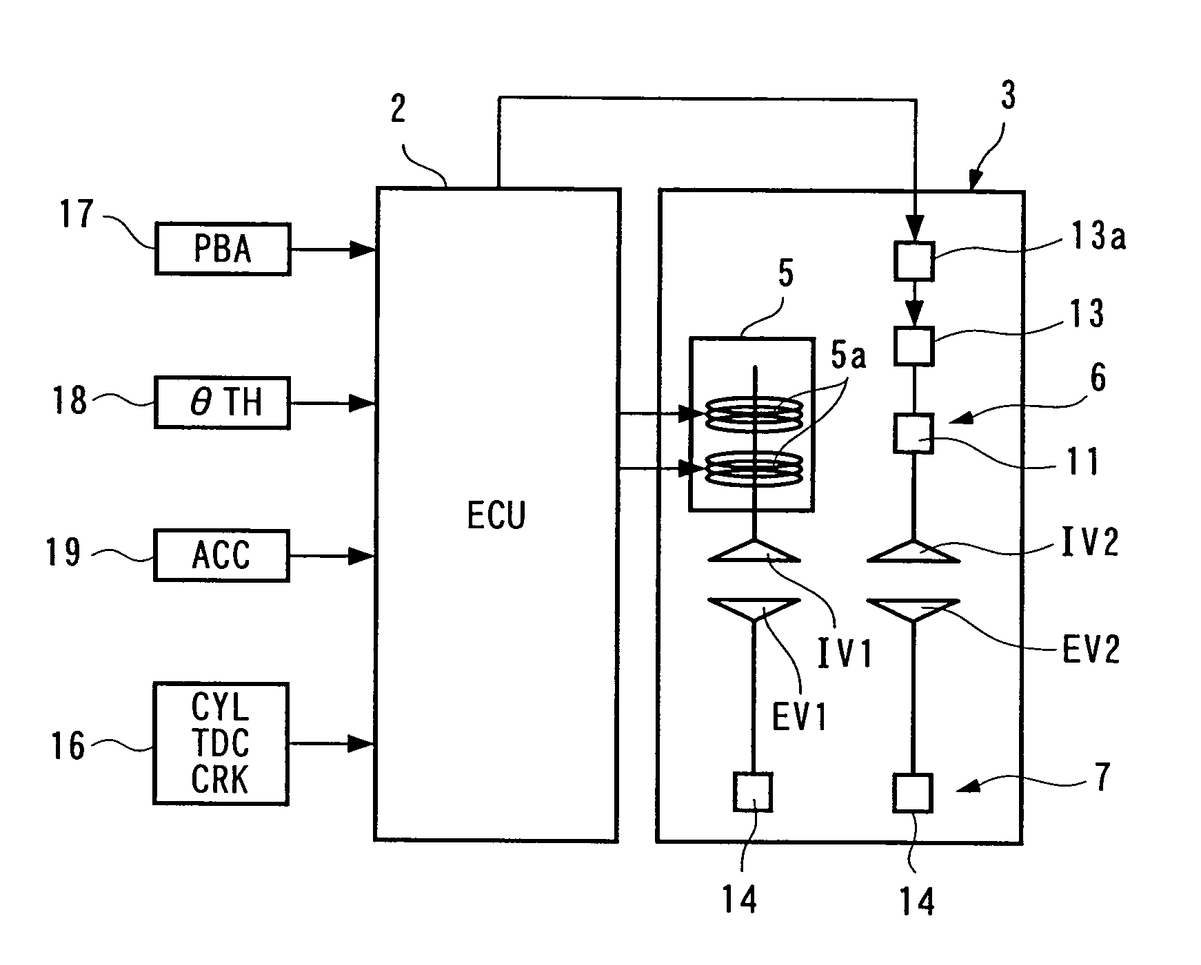
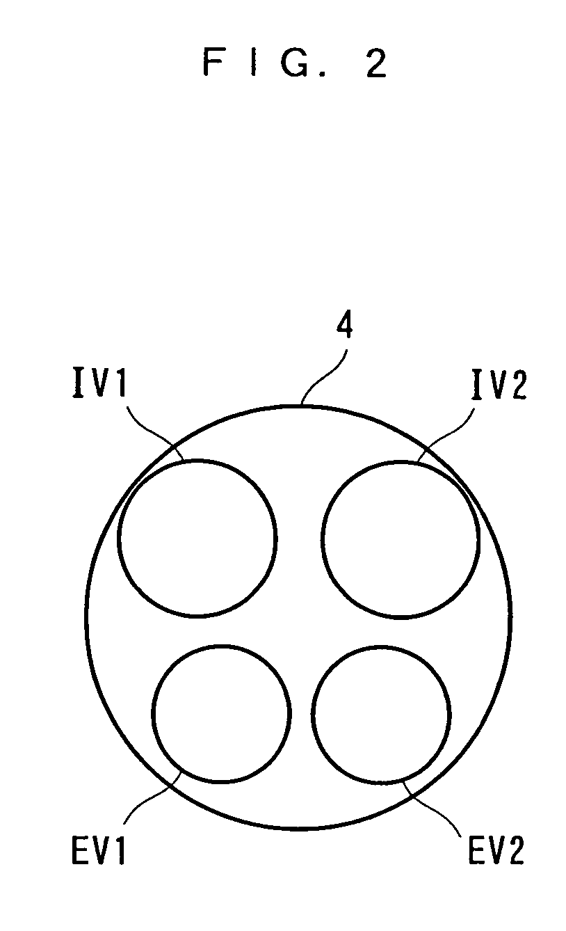
[0032]In the following, a valve operation controller, a valve operation control method and an engine control unit for an internal combustion engine according to a first embodiment of the present invention will be described with reference to the accompanying drawings. FIG. 1 generally illustrates the valve operation controller according to the first embodiment. An illustrated internal combustion engine (hereinafter simply called the “engine”) 3 is a straight four-cylinder (two cylinders are illustrated in FIG. 3) SOHC type gasoline engine equipped in a vehicle, not shown. As shown in FIG. 2, each cylinder 4 is provided with a first and a second intake valve IV1, IV2, and a first and a second exhaust valve EV1, EV2. In this embodiment, the first intake valve IV1 is driven by an electromagnetic valve operating mechanism 5 to open and close; the second intake valve IV2 by a cam type valve operating mechanism 6; and both exhaust valves EV1, EV2 by a cam type exhaust valve operating mecha...


PUM


Abstract

A valve operation controller for an internal combustion engine is provided for optimally setting a valve opening timing and a valve closing timing for an intake valve in accordance with an operating state of the internal combustion engine to improve the fuel efficiency and power of the internal combustion engine, eliminate fuel stagnation in the intake valve and sticking of the intake valve with its valve seat, and reduce the cost and weight. The valve operation controller controls open / close operations of exhaust valves (EV1, EV2) and first and second intake valves (IV1, IV2) arranged in one cylinder (4). An electromagnetic valve operating mechanism (5) electromagnetically opens / closes the first intake valve (IV1). A cam type valve operating mechanism (6) opens / closes the second intake valve (IV2) with an intake cam (11) arranged on a cam shaft (10) driven in synchronism with rotation of the internal combustion engine (3). The cam type valve operating mechanism (6) can generate a cylinder flowage within a combustion chamber of the cylinder (4). An ECU (2) controls operations of the electromagnetic valve operating mechanism (5) and the cam type valve operating mechanism (6).

Description

TECHNICAL FIELD[0001]The present invention relates to a valve operation controller for an internal combustion engine which has an exhaust valve and a plurality of intake valves arranged in one cylinder.BACKGROUND ART[0002]A variety of valve operation controllers have been conventionally proposed for variably controlling opening / closing timings and lift amounts of an intake valve and an exhaust valve in order to appropriately tuning the intake / exhaust performance in accordance with an operating state of an internal combustion engine. As one of such conventional valve operation controllers, there has been known a type of controller which changes the phase of an intake cam (hereinafter called the “cam phase”) for a cam shaft (see, for example, Laid-open Japanese Patent Application No. 7-301144). This type of valve operation controller continuously changes the valve phase to continuously control opening / closing timings of an intake valve. For example, when an engine is heavily loaded, t...

Claims


Application Information

Patent Timeline
Patent Type & Authority Patents(United States)
IPC IPC(8): F01L9/04F01L1/053F01L1/18F01L1/26F01L9/20F01L13/00F02B31/00F02B31/02F02B31/06F02D13/02F02D41/02F02D41/04
CPCF02D13/0257F02D13/0261F01L1/053F01L1/26F01L9/04F01L13/0005F01L1/18F02B31/06F02B2031/006Y02T10/18F01L2105/00F01L2800/00F01L2305/00Y02T10/12F01L9/20F02B31/085F02D13/02
Inventor SHIMIZU, YASUOYAMAKI, TOSHIHIROSAKAI, HISAO
Owner HONDA MOTOR CO LTD
Learn More