Control system for a plant using identified model parameters
a control system and model parameter technology, applied in the direction of electric controllers, electric control, instruments, etc., can solve the problems of insufficient control performance, unstable control performed by sliding mode controllers, and change in model parameters, so as to improve controllability of throttle valve opening to the target opening, accurate prediction value, and control more stably
- Summary
- Abstract
- Description
- Claims
- Application Information
AI Technical Summary
Benefits of technology
Problems solved by technology
Method used
Image
Examples
first embodiment
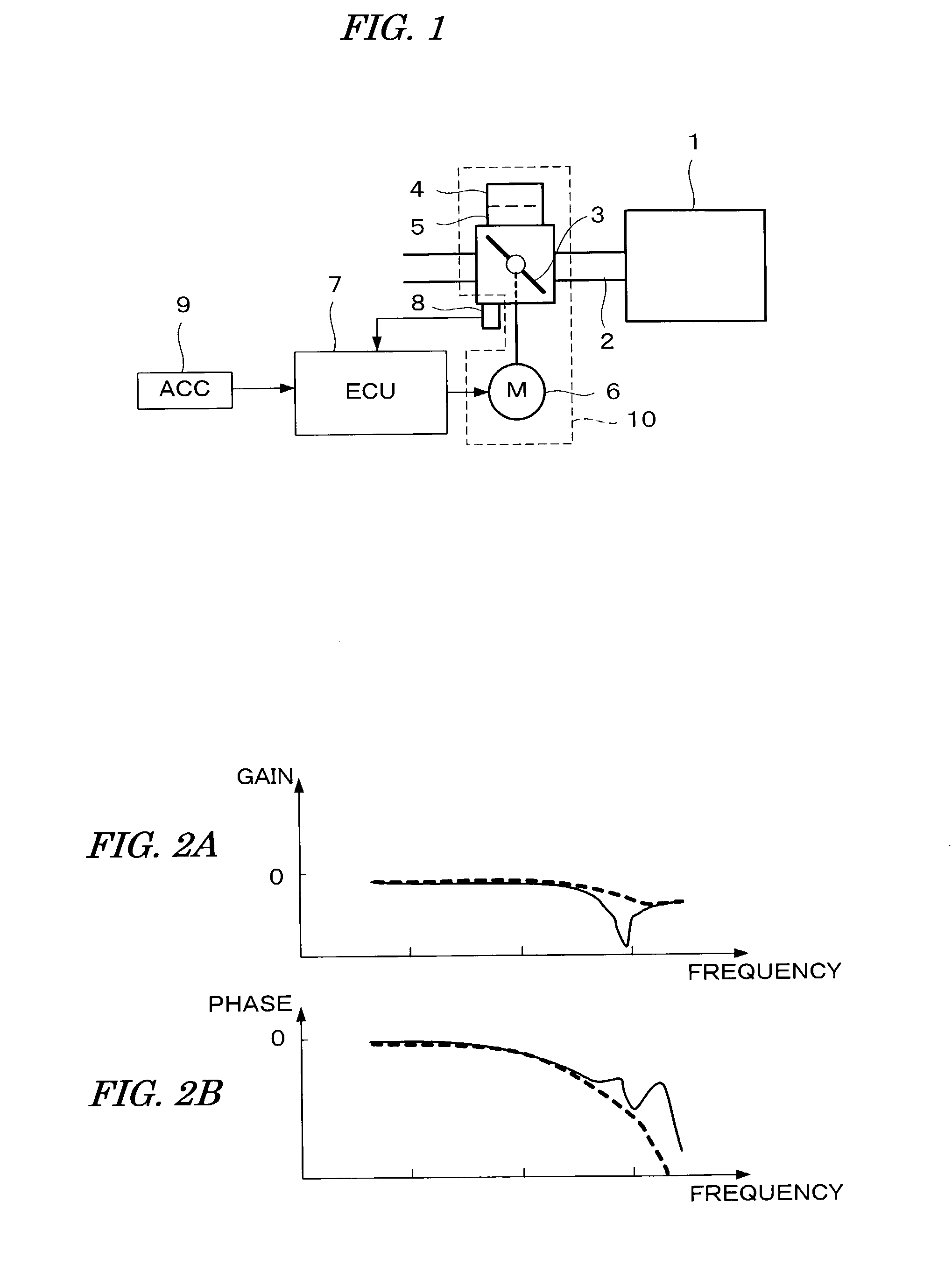
[0139]FIG. 1 schematically shows a configuration of a throttle valve control system according to a first embodiment of the present invention. An internal combustion engine (hereinafter referred to as “engine”) 1 has an intake passage 2 with a throttle valve 3 disposed therein. The throttle valve 3 is provided with a return spring 4 as a first energizing means for energizing the throttle valve 3 in a closing direction, and a resilient member 5 as a second energizing means for energizing the throttle valve 3 in an opening direction. The throttle valve 3 can be actuated by a motor 6 as an actuating means through gears (not shown). When the actuating force from the motor 6 is not applied to the throttle valve 3, an opening TH of the throttle valve 3 is maintained at a default opening THDEF (for example, 5 degrees) where the energizing force of the return spring 4 and the energizing force of the resilient member 5 are in equilibrium.
[0140]The motor 6 is connected to an electronic control...
second embodiment
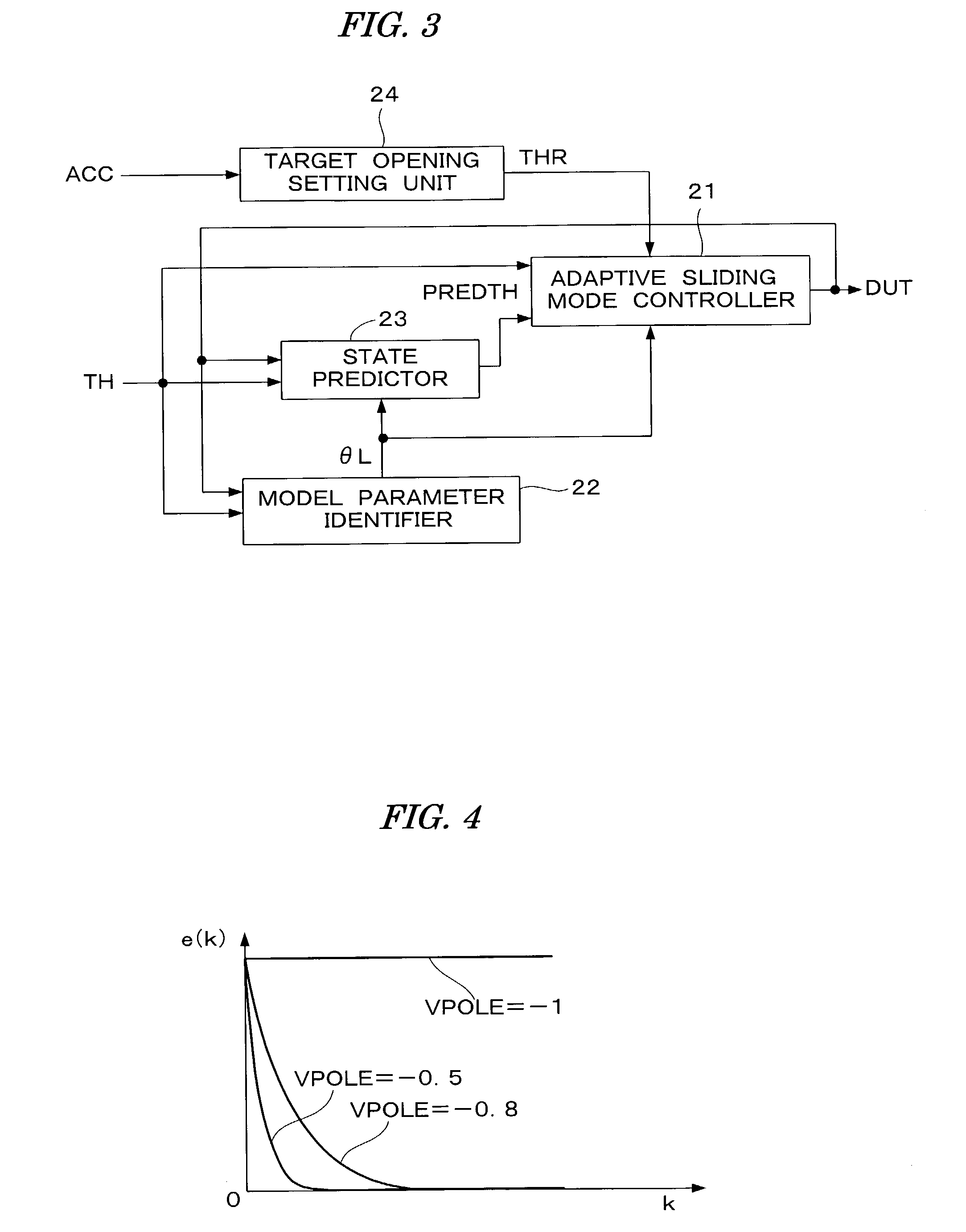
[0318]In the first embodiment described above, the controlled object model is defined by the equation (1) including the dead time d, and the predicted deviation amount PREDTH after the elapse of the dead time d is calculated with the state predictor 23, to thereby control the controlled object model which includes the dead time. Accordingly, it is necessary to execute calculations corresponding to the state predictor 23 in the CPU, and the amount of calculations executed by the CPU becomes large. In the second embodiment, in order to reduce the calculation load on the CPU, the controlled object model is defined by the following equation (1a) where the dead time d is set to “0”, and the modeling error caused by setting the dead time d to “0” is compensated by the robustness of the adaptive sliding mode control.
[0319]DTH(k+1)=a1×DTH(k)+a2×DTH(k-1)+b1×DUT(k)+c1(1a)
[0320]In order to further reduce the calculation load on the CPU, the fixed gain algorithm is employed as the algorithm...
third embodiment
MODIFICATION OF THIRD EMBODIMENT
[0398]FIG. 43 shows a modification of the control system shown in FIG. 42. In the modification, a plant 101a, instead of the plant 101 shown in FIG. 42, is a controlled object. The plant 101a is constituted by adding a flow rate sensor 113 and a feedback controller 114 to the plant 101 shown in FIG. 42. The flow rate sensor 113 detects an output flow rate V1 of the flow control valve 111, and the feedback controller 114 controls the flow control valve 111 to make an output V2OUT of the flow rate sensor 113 coincide with a flow rate corresponding to the second control quantity U2.
[0399]The modeling and the control process which are the same as those of the third embodiment are also applicable to the plant including the local feedback loop as shown in FIG. 43.
[0400]Since the circuit for energizing the motor in the first embodiment is already known, this circuit has not been described in detail. The circuit for energizing the motor may include a current ...
PUM
 Abstract
Description
Claims
Application Information
 - R&D
- Intellectual Property
- Life Sciences
- Materials
- Tech Scout
- Unparalleled Data Quality
- Higher Quality Content
- 60% Fewer Hallucinations
Browse by: Latest US Patents, China's latest patents, Technical Efficacy Thesaurus, Application Domain, Technology Topic, Popular Technical Reports.
© 2025 PatSnap. All rights reserved.Legal|Privacy policy|Modern Slavery Act Transparency Statement|Sitemap|About US| Contact US: help@patsnap.com


