Generator for producing photon number state

a generator and photon technology, applied in the direction of digital transmission, instruments, securing communication, etc., can solve the problems of detectors not being able to detect the presence of unauthorized listeners, unable to detect the incident of a plurality of photons, and unable to obtain the information on the number of incident photons

Inactive Publication Date: 2006-05-23
MITSUBISHI ELECTRIC CORP
View PDF5 Cites 7 Cited by
  • Summary
  • Abstract
  • Description
  • Claims
  • Application Information

AI Technical Summary

Benefits of technology

[0011]The present invention was achieved to solve these problems, and it is an object of the present invention to provide a device that can suppress uncorrelated two or more photons from being contained in the response time of the detector, to generate an accurate of correlated photons in one pulse, and to control the timing of photon generation in a pulse.

Problems solved by technology

However, if the same information is loaded on two or more photons, the unauthorized listener may utilize a part of these photons and the presence of the unauthorized listener may not be able to be detected.
However, if the detector used in the conventional technique is used as a photon detector as it is, when a plurality of photons were incident in a response time of the detector, the detector was unable to detect that a plurality of photons were incident.
For example, in AQ-APD, since the amplitude of the pulse becomes constant irrespective of the number of incident photons, it was able to detect that photons were incident but it was unable to obtain the information on the number of incident photons.
In addition, when the photo-multiplier tube is used, the quantum efficiency η is as low as about 20% at maximum, and the detection efficiency of two photons is extremely low (4%) because the efficiency is equal to the square of η, and it was unable to detect the incidence of two or more photons.
In the conventional technique, because the use of these detectors was premised, there was no means for judging the number of incident photons.
Consequently, even when a plurality of photons are generated sequentially from a parametric fluorescent pairs within a range of the response time of the detector, the detector opens the gate, causing a problem in that a two-photon-state emerges.
However, on the other hand, it was impossible to generate the “two-photon-state” in which two photons sequentially exist within a range of the response time of the detector.
As described above, because in the conventional technique, the detector was unable to detect the number of incident photons and had no means for judging the number of incident photons, the detector had a drawback in that even if photon pairs were generated sequentially within the response time of the photon detector, it opened the gate and a state in which two or more photons were contained within the response time of the detector was emitted.
Furthermore, in the conventional method, it was unable to accurately generate a plurality of photons in one pulse.
It was also unable to control the timing of photon generation in the pulse.

Method used


Image

  • Generator for producing photon number state
  • Generator for producing photon number state
  • Generator for producing photon number state

Examples


embodiment 1

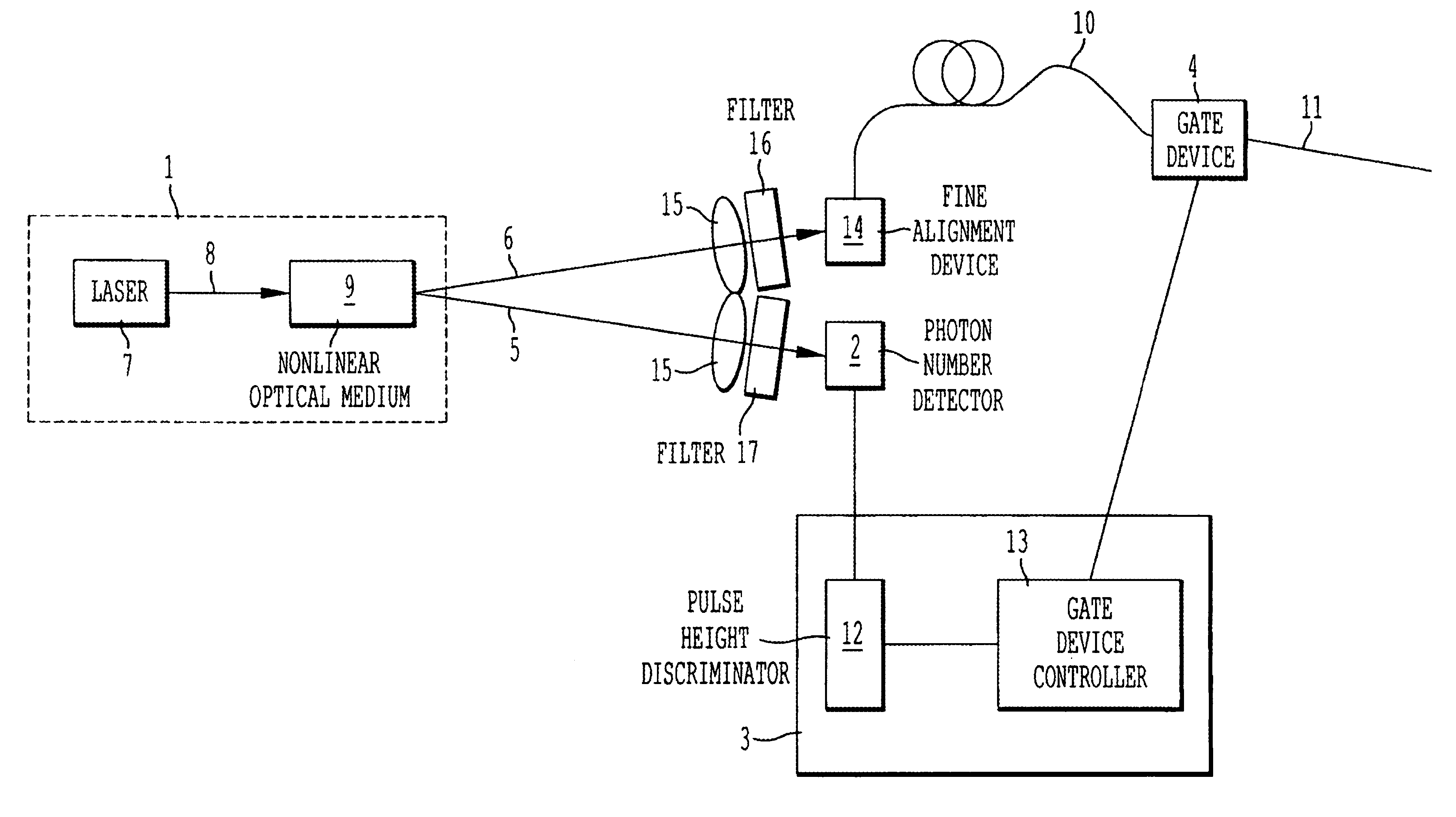
[0052]FIG. 1 is a general arrangement drawing of one embodiment of the invention. In this embodiment, it is a device in which a single photon state is generated and two photons do not densely exist within the resolution time τ of the detector.

(Description on Configuration)

[0053]In FIG. 1, numeral 1 denotes a photon pair source that generates a photon pair that correlate with the generation time, numeral 2 denotes a photon number detector for detecting an idler photon 5, and numeral 3 denotes a controller for controlling a gate device 4 in response to the information on the number of photons from the photon number detector. The gate device 4 controls the emission of a signal photon 6. The photon pair source 1 comprises a nonlinear optical medium 9 and a pumping light source 7 of a pumping light 8 that pumps the nonlinear optical medium. The idler photon 5 generated in the nonlinear optical medium 9 is converged to the photon number detector 2 via a filter 17 that allows the object id...

embodiment 2

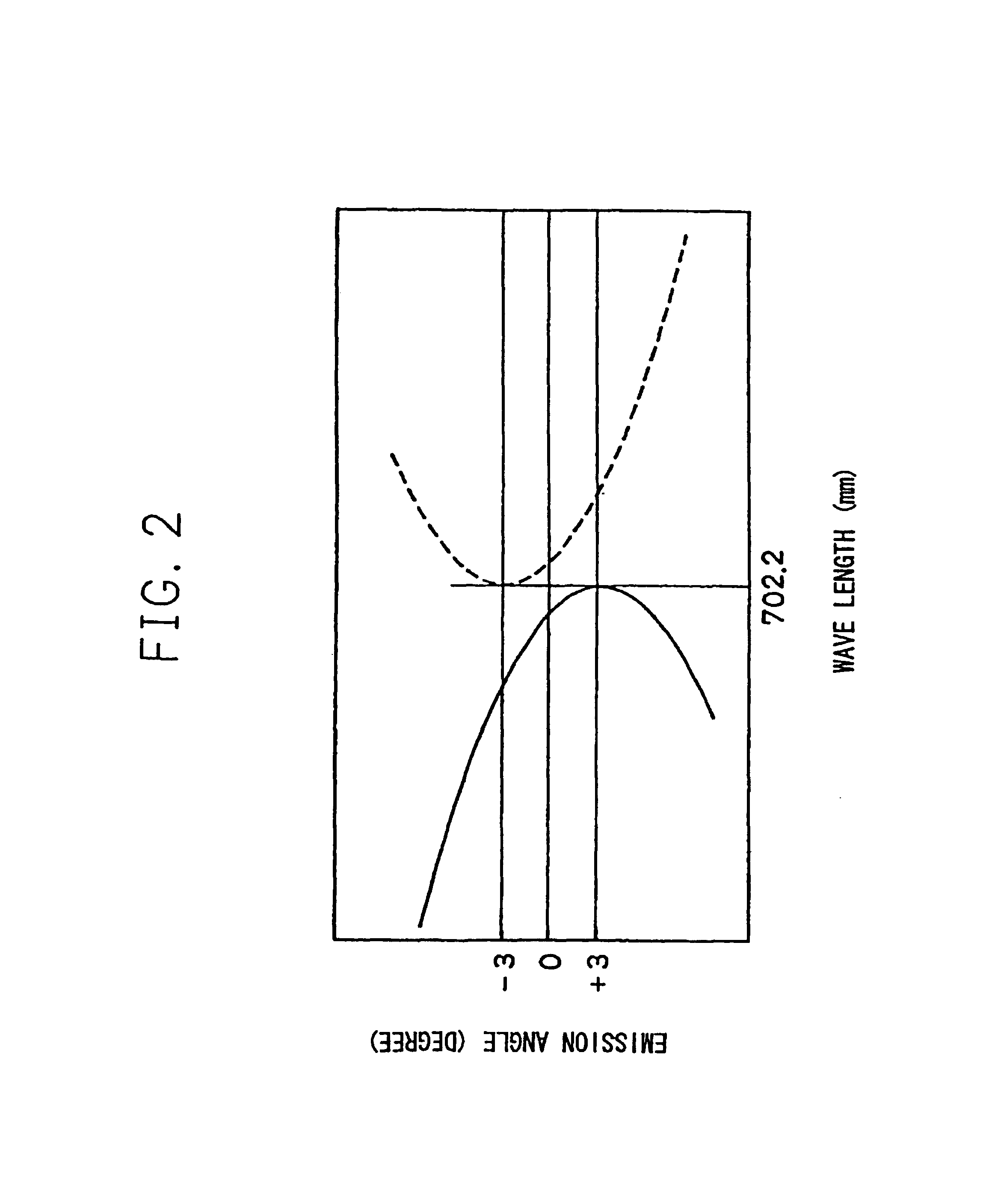
[0064]In Embodiment 1, the wavelength of signal beam generated was 702.2 nm, but needless to say, this wavelength is able to optionally changed by selecting a suitable pumping light source laser and nonlinear optical medium. For example, it is naturally possible to generate wavelengths in the vicinity of 1550 nm, vicinity of 1310 nm, and in the vicinity of 800 nm, which are generally adopted to communication using optical fiber.

[0065]The method for generating a photon pair shown in Embodiment 1 (FIG. 2) is a method suited to obtain a photon pair beam with equal wavelengths and small angular dispersion, but it is possible to obtain a photon pair with different wavelengths by changing the optical axis direction of the BBO crystal for other object of use. In such event, the two tuning curves of FIG. 2 come in contact with straight lines that correspond to different wavelengths, respectively. In such event as well, the photons are taken out at an angle in which the tuning curves shown i...

embodiment 3

[0068]FIG. 5 shows another embodiment of the invention. In this embodiment, numeral 7 is a pumping light source, numeral 18 an optical fiber for guiding the pumping light, numeral 19 a waveguide channel type nonlinear medium, numeral 20 a waveguide channel type filter for discriminating the fluorescent pair and pumping lights generated from the waveguide channel type nonlinear optical medium 19, numeral 21 an emission port of pumping light, and numeral 22 a waveguide channel type filter for dividing the fluorescent pair into two branches.

[0069]In this embodiment, the parametric fluorescent pair is generated in the waveguide channel type nonlinear optical medium 19. The fluorescent pair has vertical and horizontal polarized lights, respectively, and in the waveguide type filter 22 that operates as a polarizing beam splitter, that with one of the polarized light pair is transmitted to the photon number detector 2 and another to the optical fiber 10.

[0070]By this kind of configuration,...


PUM


Abstract

An apparatus for generating a specified number of photons whose generating time is known, and further an apparatus for generating a specified number of photons in the known schedule are provided. The particularly important specified number is 1 and it is able to be applied to quantum cryptographic communication. The apparatus comprises a photon pair source for generating a photon pair that comprises a signal photon and an idler photon and correlates with the generating time, photon number detectors for detecting the photon number of idler photons, a controller for controlling the gate device in conformity with the information on the photon number form the photon number detector, and a gate device for controlling the emission of the signal photon.

Description

TECHNICAL FIELD[0001]The present invention relates to a device for generating a specified number of photons with known generating time, and more specifically, to a device for generating a specified number of photons in a known schedule. The particularly important specified number is 1, which is able to be used for quantum cryptographic communication.BACKGROUND ART[0002]In the quantum cryptographic communication system, loading each photon with information enables the detection of an unauthorized listener by the quantum mechanical principle. However, if the same information is loaded on two or more photons, the unauthorized listener may utilize a part of these photons and the presence of the unauthorized listener may not be able to be detected. In this way, ideally, a pulse that contains only one photon at maximum must be used. For this kind of pulse, it is popularly practiced to attenuate the light beam from the laser beam source by an attenuator in such a manner that the mean numbe...

Claims


Application Information

Patent Timeline
IPC IPC(8): H01J40/14G02F1/39H04L9/08
CPCH04L9/0852H04B10/50G02F1/39
Inventor TAKEUCHI, SHIGEKI
Owner MITSUBISHI ELECTRIC CORP
Why Eureka
Try Eureka