
Plastic profile

Inactive Publication Date: 2006-05-23
TDINDUSTRIES
View PDF8 Cites 32 Cited by
  • Summary
  • Abstract
  • Description
  • Claims
  • Application Information

AI Technical Summary

Benefits of technology

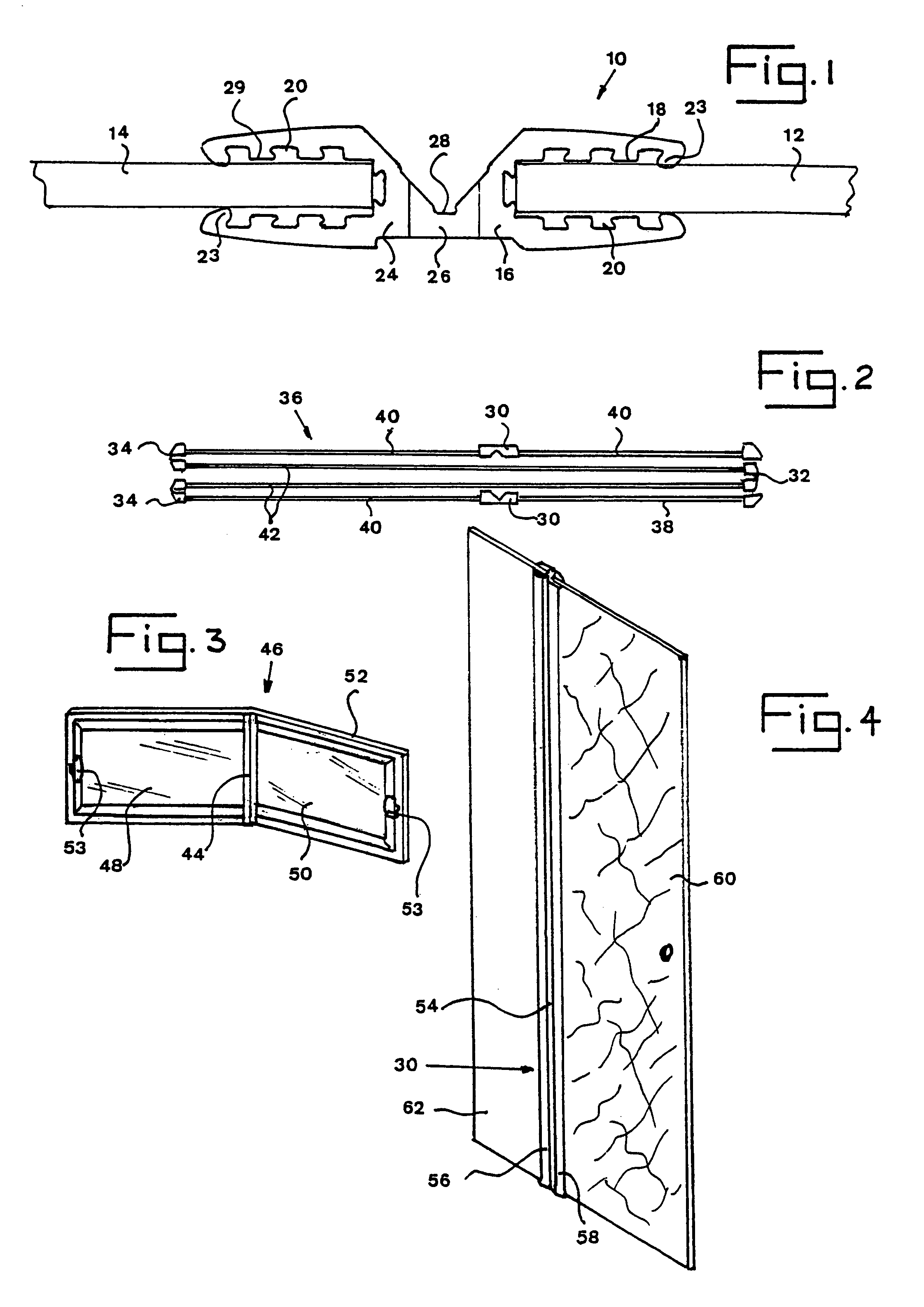
[0016]It will be realized that the novel profile of the present invention serves in a new application which was not possible with previous designs. Since it was found that such a variable angle connector profile could be manufactured to have an operating life exceeding 10,000 bend cycles, it became possible to use the profile as a hinge for a door or window. An important advantage of this type of hinge is that, due to continuity of material, there is no leakage path at any angle of use, and so no seal elements are required. Obviously, such inherent sealing is a significant advantage in the construction of a shower stall.
[0018]The three segments forming the connector profile unit of the present invention could be extruded separately and joined, when cold, by an suitable fabrication technique. However, the use of coextrusion produces a superior joint at lower cost and is inherently completely leakproof.

Problems solved by technology

However, it is sometimes advantageous to allow some of the corners to form an angle that is other than 90 degrees.
a) For space reasons, the panels could not be preassembled as shower enclosures in the factory, stored and transported to the user as one unit.
b) Although panel assembly at different angles was possible, such angles were still limited to increments of about 20°, according to the ridges on the outer face of the multi-functional profile.

Method used


Image

  • Plastic profile
  • Plastic profile
  • Plastic profile

Examples


embodiment 10

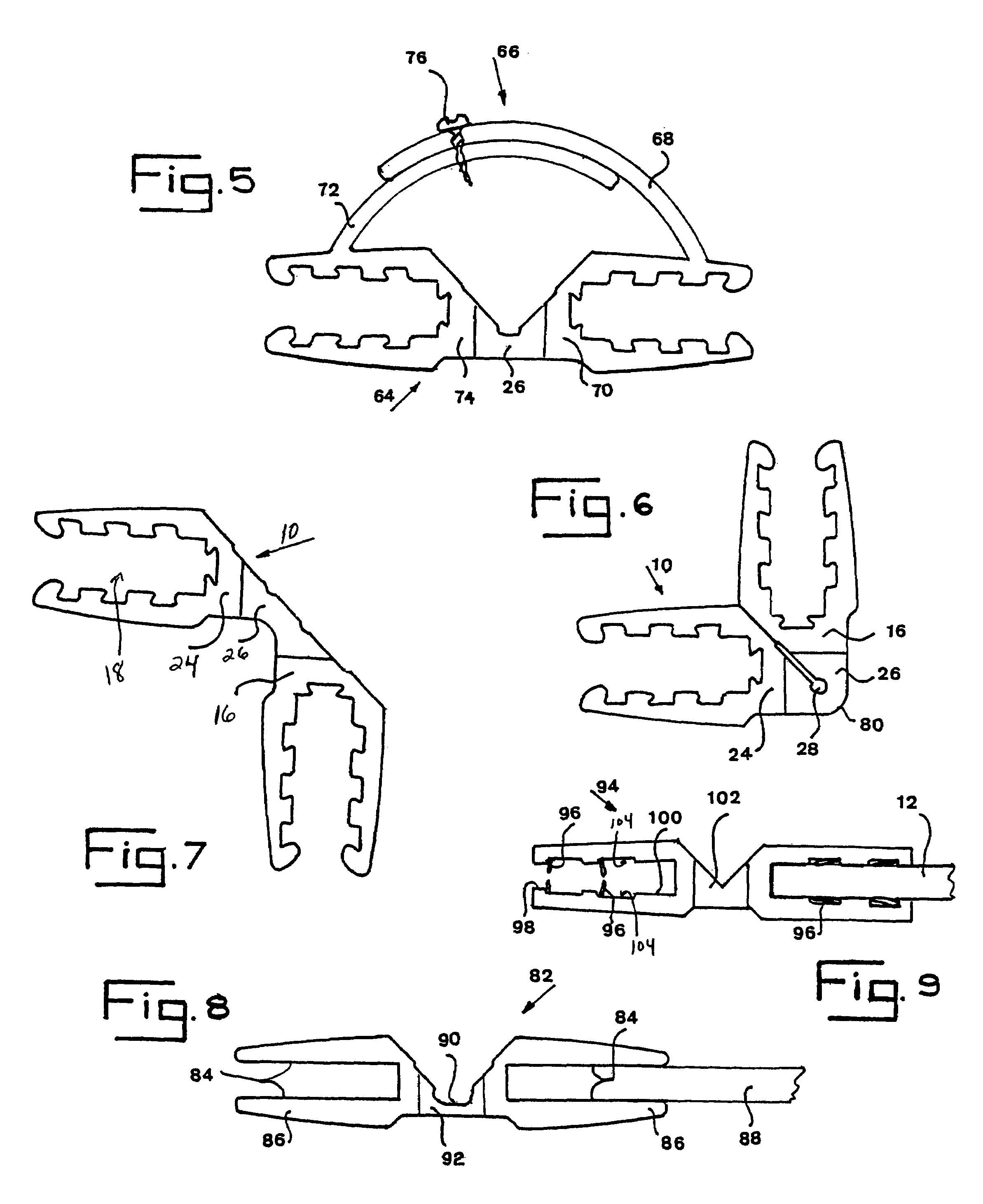
[0047]FIG. 6 illustrates the embodiment 10 shown in FIG. 1, bent inward to its limit, which in this example is 90 degrees. It will be noted that the recess 28 now forms center hole 78. The outer corner 80 also forms part of a circle, thus reducing stress concentration and contributing to the long life of the profile unit.

[0048]FIG. 7 illustrates the profile 10 bent outward 90 degrees. It will be noted that even further bending is possible. Re-examining FIG. 2, it will be seen that the profile units 32 are bent 180 degrees, or very close to that angle. Such severe bending is, however, usually carried out only once or twice when the enclosure is folded, and so there is no material fatigue problem.

embodiment 82

[0049]Seen in FIG. 8 is a further embodiment 82 of the profile unit shown in FIG. 1. However, in this embodiment, the inner faces 84 of the open channels 86 are smooth. The channels 86 are appropriate for use when the enclosure panel 88 to be inserted therein is to be attached by means of an adhesive instead of a sealant. The center 90 of the flexible middle segment 92 has a thin section to reduce bending stresses.

embodiment 94

[0050]An additional embodiment 94 of the profile unit of FIG. 1 is illustrated in FIG. 9. In this embodiment of the profile unit 94, the inner faces 98 of the channels 100 include deflectable retaining members 96 that extend outwardly from respective recesses 104 toward the center of the channel 100. The retaining members 96 help to maintain the position of a panel 12 within a channel 100. As a panel 12 is inserted into the unit 94, these retaining members 96 engage the panel 12 and deflect into their respective recesses 104 as the panel 12 moves within the channel 100 (FIG. 9). The flexible middle segment 102 has an area of reduced thickness to permit bending.


PUM

PropertyMeasurementUnit
Thicknessaaaaaaaaaa
Thicknessaaaaaaaaaa
Thicknessaaaaaaaaaa

Abstract

The invention provides a variable angle connector profile for connecting a plurality of enclosure panels, the profile comprising: a first end segment having a first open channel sized for receiving a first enclosure panel; a flexible middle segment attached to the first end segment; and a second end segment attached to the middle segment and having a second open channel sized for receiving a second enclosure panel; the middle segment including a flexible plastic material and the end segments including at least a semi-rigid material, all three segments being co-extruded as a single integral linear unit and wherein each of the first and second end segments includes surfaces adapted to abut each other and to delimit the extent of movement of the end segments towards each other in a first sense of swivel from a linear alignment of 180° to a substantially perpendicular alignment of about 90°, while the segments are free to move in a second sense of swivel away from the surfaces to form a reflex angle therebetween, for accordian-like folding, storage and transport of a plurality of panels interconnected therewith.

Description

CROSS-REFERENCE TO RELATED APPLICATIONS[0001]This application is a Continuation-In-Part of U.S. Ser. No. 10 / 280,126 filed Oct. 25, 2002, now abandoned, which application is incorporated herein by reference in its entirety.BACKGROUND OF THE INVENTION[0002]The present invention relates to a plastic profile which is angularly adjustable. More particularly, the invention provides a plastic profile which can either be set to a desired angle, or can be used as a door or window hinge. The profile is of particular utility in the construction of a shower stall.[0003]In our Israel Specification No. 117,154 there is described a prefabricated vertical shower stall made of several panels, corner connecting profiles and other components. Shower stalls of this type are often square or rectangular in plan view. However, it is sometimes advantageous to allow some of the corners to form an angle that is other than 90 degrees. Such a requirement may arise when the enclosure is to be erected in a non-r...

Claims


Application Information

Patent Timeline
IPC IPC(8): A47K3/022A47K3/00A47K3/30E05D1/02E05D5/02
CPCA47K3/30E05D1/02E05D5/0246E05Y2600/526E05Y2900/114Y10S16/13Y10T16/525E05Y2800/672
Inventor TAVIVIAN, AHARON
Owner TDINDUSTRIES
Learn More