
Optical fiber, Raman amplifier, and optical communication system

a technology of optical communication system and amplifier, which is applied in the field of optical fiber, raman amplifier, optical communication system, can solve the problems low raman amplification gain, and inability to achieve high raman gain of signal light, and achieve the effect of low pumping power

Active Publication Date: 2006-05-16
FURUKAWA ELECTRIC CO LTD
View PDF2 Cites 10 Cited by
  • Summary
  • Abstract
  • Description
  • Claims
  • Application Information

AI Technical Summary

Benefits of technology

The present invention provides an optical fiber, distributed Raman amplifier, and optical transmission line that can effectively amplify with lower pumping power. The optical fiber has specific properties such as a cable-cutoff wavelength, mode-field diameter, transmission loss, and dispersion. The distributed Raman amplifier uses this optical fiber as an amplifying medium, and the optical communication system includes this optical fiber and distributed Raman amplifier as a transmission line. These technical effects can improve the efficiency and reliability of optical communication systems.

Problems solved by technology

Meanwhile, if the FWM generating efficiency increases, the pump light exploited by the FWM increases and thus the signal light cannot attain a high Raman gain.
Countermeasures against such a disadvantage using the optical fiber having a zero dispersion wavelength between the wavelengths of the signal light and the pump light is to lower the intensity of the pump light.
However, this is not a good solution since it causes a decrease in Raman amplification gain.

Method used


Image

  • Optical fiber, Raman amplifier, and optical communication system
  • Optical fiber, Raman amplifier, and optical communication system
  • Optical fiber, Raman amplifier, and optical communication system

Examples


examples

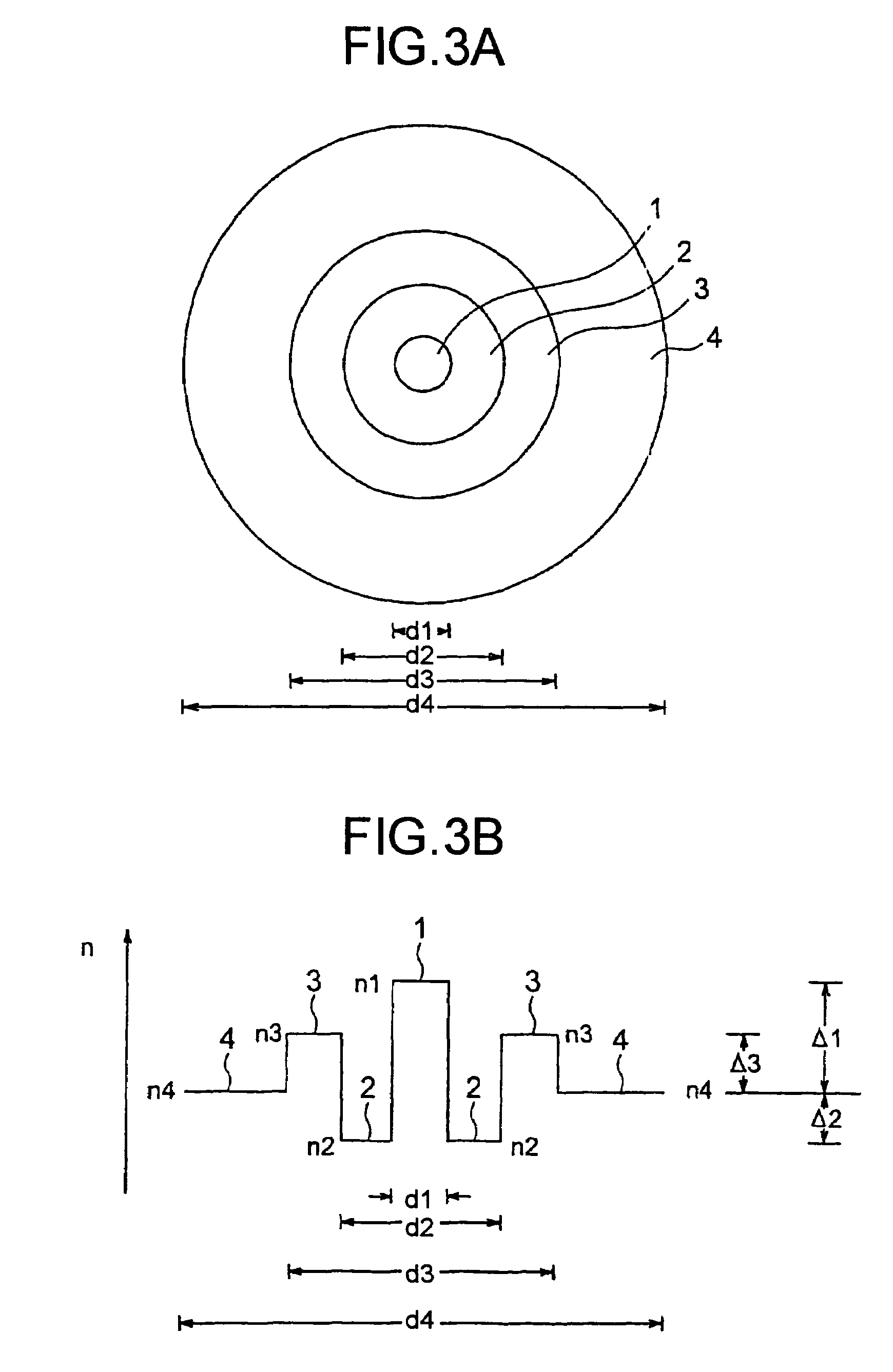
[0045]FIG. 4 is a table of parameters and characteristics of optical fibers manufactured by the above-mentioned method and constituted as illustrated in FIGS. 3A and 3B. As the optical fibers constituted as illustrated in FIGS. 3A and 3B, six types of optical fibers are manufactured each with varied relative refractive index differences Δ1 to Δ3 and varied diameters d1, d2, and d3 (micrometers).

[0046]It is assumed herein that the diameters d1, d2, and d3 are defined as follows. The diameter d1 is a diameter of the first core 1 at a position at which the first core 1 is equal in refractive index to the cladding 4. The diameter d2 is a diameter of the second core 2 at a position on a boundary between the second core 2 and the third core 3 and at which the second core 2 has a refractive index of a half of Δ2. The diameter d3 is a diameter of the third core 3 on a boundary between the third core 3 and the cladding 4 and at which the third core 3 has a refractive index of a one-tenth of ...


PUM

PropertyMeasurementUnit
cable-cutoff wavelengthaaaaaaaaaa
mode-field diameteraaaaaaaaaa

Abstract

An optical fiber, which is employed as a transmission line of an optical communication system, has a cable-cutoff wavelength of not longer than 1430 nanometers at the wavelength of 1450 nanometers, a mode-field diameter of not less than 7 micrometers and not more than 9 micrometers, a transmission loss of not more than 0.285 dB / km, and a dispersion of 0.1 to 4 ps / nm / km.

Description

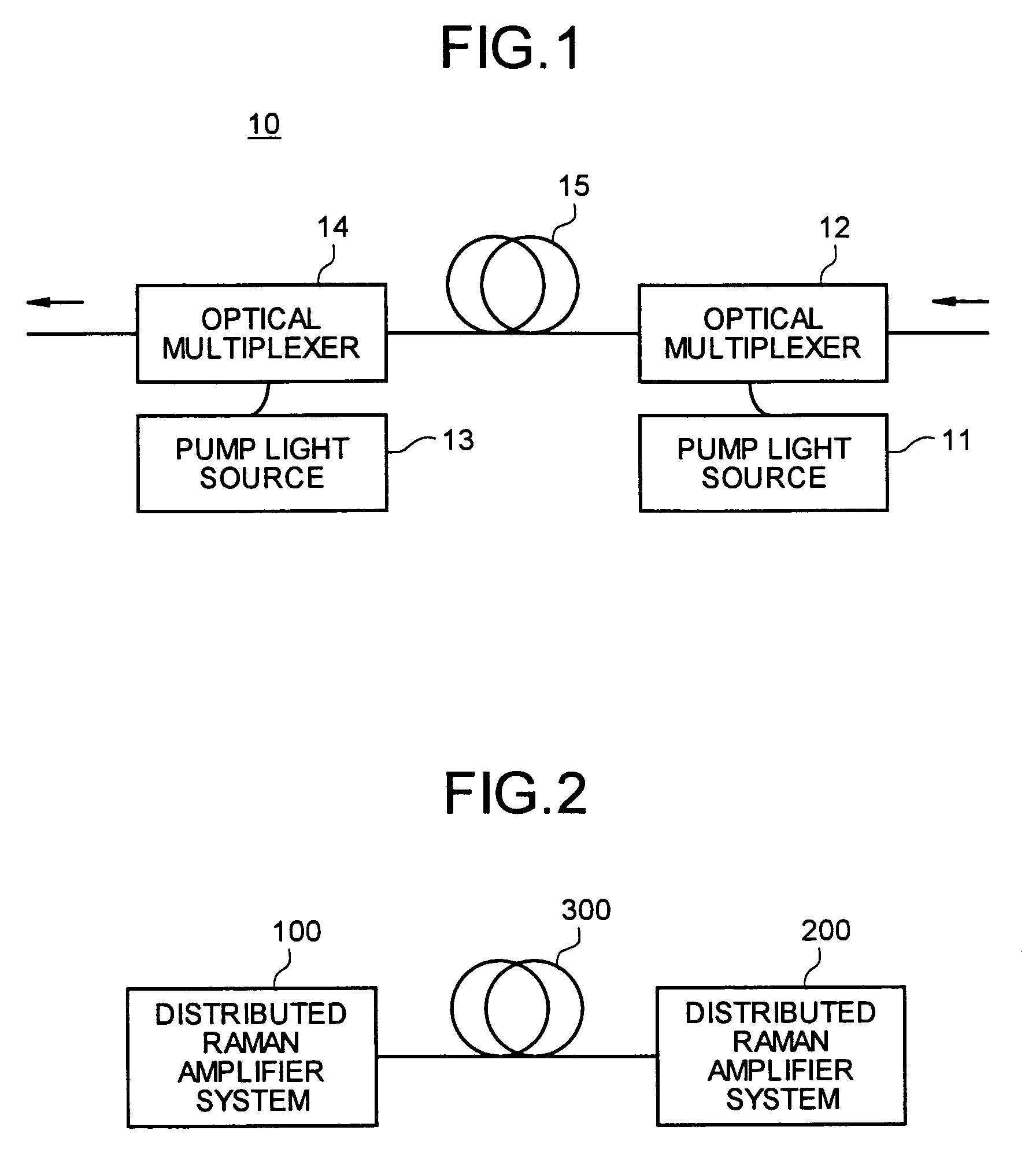
BACKGROUND OF THE INVENTION[0001]1) Field of the Invention[0002]The present invention relates to an optical fiber, a Raman amplifier using the optical fiber, and an optical communication system using the optical fiber.[0003]2) Description of the Related Art[0004]A Raman amplifier is characterized in that the optical signal transmission distance is extended and noise in optical fiber transmission is reduced. As the Raman amplifier, a distributed Raman amplifier and a discrete Raman amplifier are known.[0005]The distributed Raman amplifier includes of first and second pump light sources, optical multiplexers and an optical fiber. This distributed Raman amplifier is also applied to the embodiment of the present invention.[0006]Meanwhile, the discrete Raman amplifier is an optical amplifier constituted so that an amplified light is inputted to an optical fiber in an enclosed device, for example, accommodates the coiled optical fiber and is installed in a relay station, such as a dispers...

Claims


Application Information

Patent Timeline
Patent Type & Authority Patents(United States)
IPC IPC(8): G02B6/02G02B6/036C03B37/027G02B6/00G02F1/35G02F1/39H01S3/10H01S3/30
CPCG02B6/02004H01S3/302G02B6/03644G02B6/02271
Inventor SUGIZAKI, RYUICHIYAGI, TAKESHI
Owner FURUKAWA ELECTRIC CO LTD
Learn More