
Image processing apparatus and program

a technology of image processing and program, applied in the field of image processing, can solve the problems of large degree of visible image quality deterioration, blurring phenomenon essentially occurring, and the entire image may become blurred, and achieve the effect of enlarged image and effectively using the featur

Active Publication Date: 2006-05-16
FUJIFILM BUSINESS INNOVATION CORP
View PDF8 Cites 64 Cited by
  • Summary
  • Abstract
  • Description
  • Claims
  • Application Information

AI Technical Summary

Benefits of technology

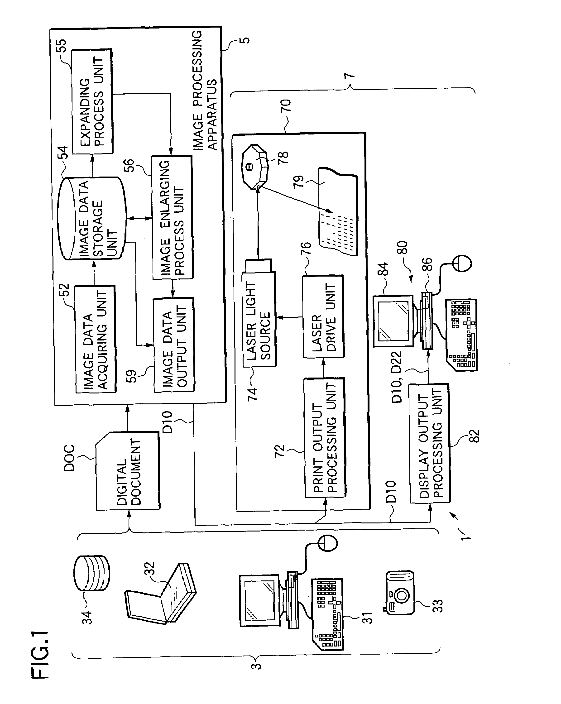
[0020]The present invention has been made to solve the above-described conventional problems, and therefore, has an object to provide both an image processing apparatus and a program, which are capable of enlarging an image, while a balance with respect to processing time is secured, and occurrences of image deteriorations such as a blurring phenomenon, jaggy, and a block distortion are prevented.

Problems solved by technology

However, these interpolating / enlarging methods own such a trend that a blurring phenomenon essentially occurs.
Although the nearest neighbor method can execute the high-speed processing operation due to the simple processing operation and the small calculation amount, since one pixel of an original image is directly enlarged in a rectangular shape, there are large degrees of visible image quality deteriorations.
In the bilinear method, since the smoothing (low-pass filtering) effect is emphasized, an entire image may become blurred.
That is, edge portions are mainly smoothed by the low-pass filtering effect, while such an assumption that an image is changed in a linear manner cannot be applied to the edge portions.
Since the calculation amount of the cubic convolution method becomes larger than the calculation amounts of other two methods and the reference range thereof become larger, this cubic convolution method is not suitable when high-speed processing operation is required.
However, in the enlarging method using the iterated conversion coding operation, since the enlarged image is produced by iterating a predetermined process operation, the processing time thereof would become considerably longer than that of the interpolating / enlarging method.
Furthermore, the visibly-allowable enlarged image can be hardly produced by merely executing the substituting process operation into the domain block image only one time.
As a result, since these process operations are iterated so as to acquire the enlarged image, the resultant processing time required for obtaining the visibly-allowable enlarged image would be prolonged.
Also, this fractal enlarging method newly owns another image quality deterioration problem.
That is, as to a document image and a stepped edge portion, block distortions may occur, noise-shaped trash (smear) may he produced, and oozing of splinter-shaped pixel values may occur.
Also, the conventional fractal enlarging method has a problem such that reproducibility of a busy portion is deteriorated (namely, blurring phenomenon and noise).
However, this conventional method still cannot solve the deterioration problem such that the noise-shaped trash occurs at the stepped edge portion, and also, the splinter-shaped pixel value oozes.
As a consequence, this conventional method owns such a drawback that the clear edge reproduction (namely, feature achieved by fractal enlarging method) cannot be realized, so that the resultant image becomes blurred.
However, since the restriction in the range block image seeking range based upon the use frequency has no reason in view of the image quality in this method, there is such a drawback that this restriction may cause the image quality to be deteriorated.
These image quality problems are known as the jaggy, the blurring phenomenon, and the block distortions, which may occur when the enlarged images are produced.
However, these problems could not yet been solved in a comprehensive manner.

Method used


Image

  • Image processing apparatus and program
  • Image processing apparatus and program
  • Image processing apparatus and program

Examples


first embodiment

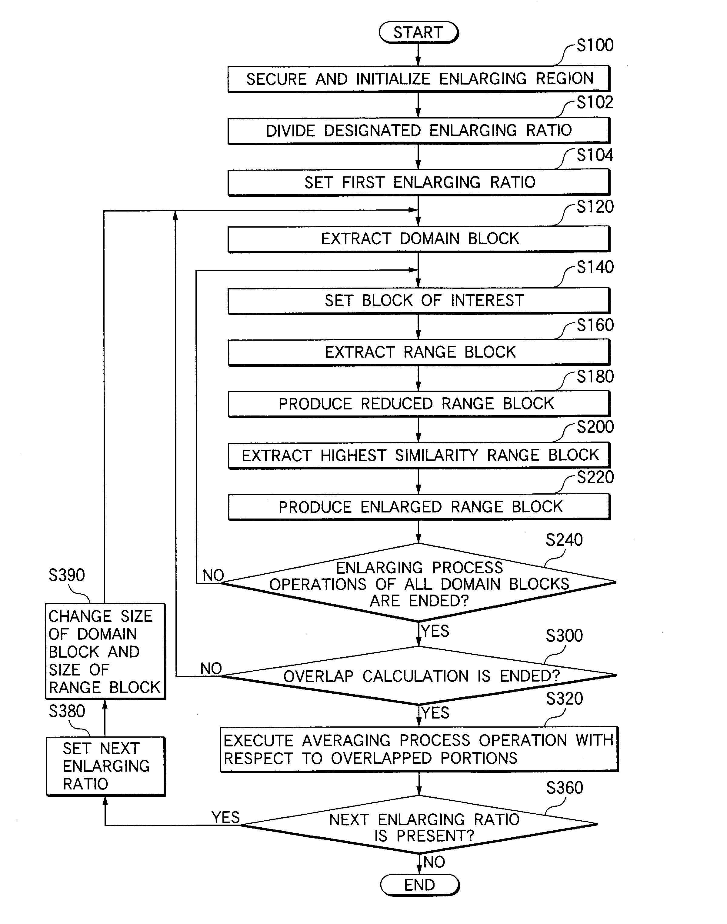
[0064]FIG. 6 is an explanatory diagram for explaining a process sequence executed in the image processing apparatus 5 according to the above-described first embodiment, more specifically, such a process sequence that an image enlarging process operation executed in the image enlarging process operation 56 is interested. FIG. 6(A) indicates a diagram for showing one example of a domain block image, a range block image, a reduced range block image, and an enlarged range block image, whereas FIG. 6(B) is a flow chart for describing a first example of the process sequence.

[0065]First of all, as an initial condition for starting the enlarging process operation, it is so assumed that subject image data which has been acquired by the image data acquiring unit 52 and will be enlarge-processed has been previously stored in the image data storing unit 54. Under such an initial condition, the image enlarging process unit 56 firstly secures a memory region in the image data storing unit 54 for ...

fifth embodiment

[0092]FIG. 9 is a diagram for illustrating one example of combinations of enlarging ratios divided by the enlarging ratio dividing unit 561. In this example shown in FIG. 9, as to such a designated enlarging ratio (for instance, designated enlarging ratio is 6, 8, 9 etc.) which may be expressed by a product of two values among the designated enlarging ratios, it is divided into two enlarging ratios. In the enlarging ratio dividing unit 561, this combination of the enlarging ratios is previously prepared as table data so that the enlarging ratio dividing unit 561 may utilize this table data. Alternatively, the enlarging ratio dividing unit 561 may calculate this combination of these enlarging ratios every time it is required. Alternatively, although the designated enlarging ratio is divided into the two enlarging ratios in this illustrated example, this designated enlarging ratio may be divided into three, or more enlarging ratios. For instance, when the designated enlarging ratio is...

second embodiment

[0093]FIG. 10 is a flow chart for describing process sequential operations executed in the image processing apparatus 5 of the The image enlarging process unit 56 firstly divides a designated enlarging ratio “r” so as to produce a combination of the divided enlarging ratios (step S102), and then sets a first enlarging ratio and executes a similar process operation to that of the above-described first example (step S104). For example, among the designated enlarging ratios, such an enlarging ratio which can be expressed by a product of two values (e.g., designated enlarging ratio is 6, 8, 9 and so on) is divided into two enlarging ratios.

[0094]Next, the process operation of the image processing apparatus 5 is explained with reference to such an example that after a two-times enlarged image (image enlarged by two times) has been formed by way of the above-described first embodiment, this enlarged image is again enlarged in the two-times enlarging ratio so as to obtain a four-times enl...


PUM


Abstract

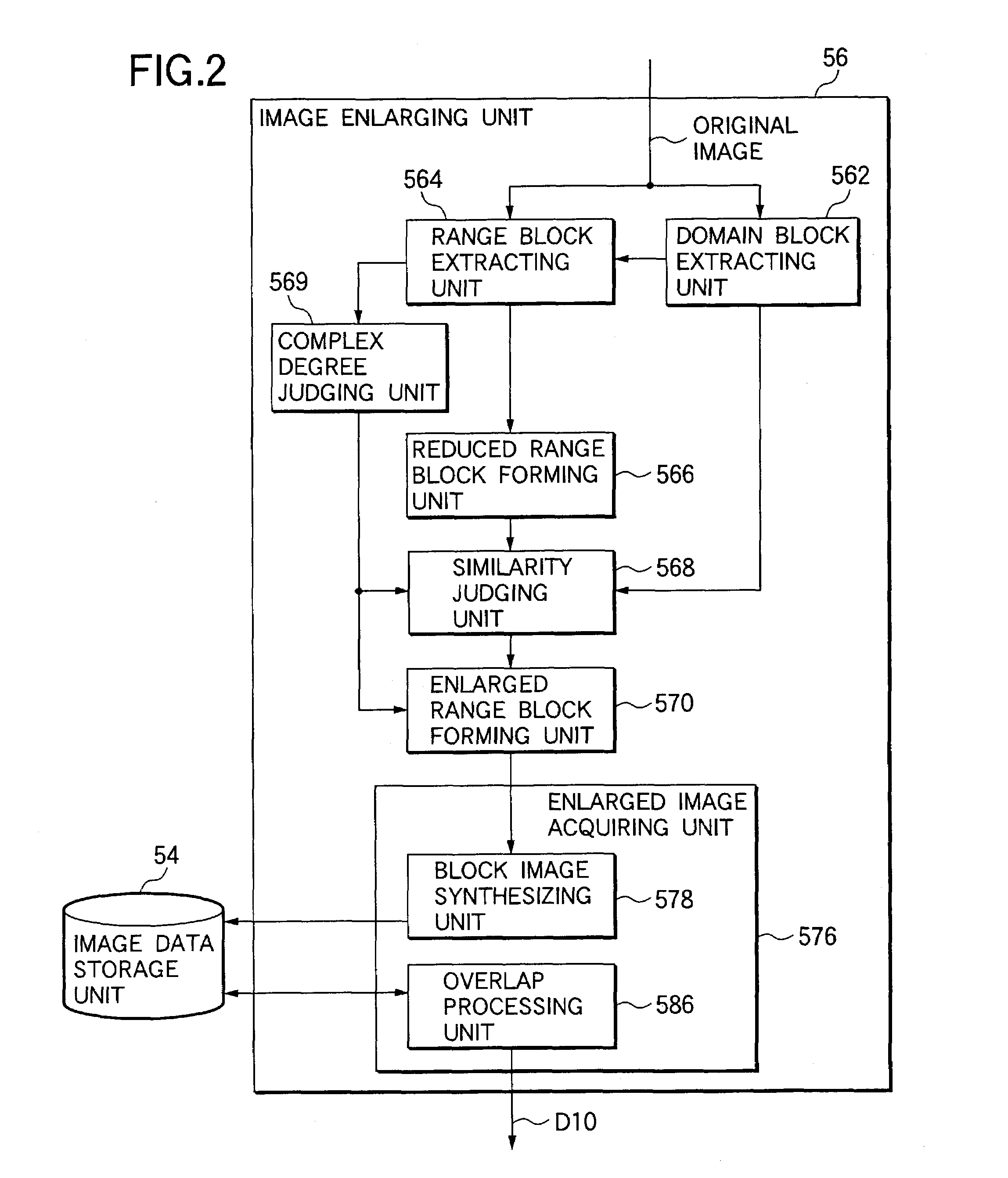
A domain block extracting unit extracts a domain block image from an original image. A range block extracting unit extracts a range block image from an area in the vicinity of the domain block image. The range block image has size being larger than a domain size and being smaller than an enlarged size. A reduced range block forming unit reduces the range block image to the domain size to produce a reduced range block image. A similarity judging unit compares each of the reduced range block images with the domain block image to select the highest similarity range block image. An enlarged range block forming unit forms an enlarged range block image by enlarging the size of the highest similarity range block image to an enlarged size thereof. An enlarged image acquiring unit produces an enlarged image of an original image by employing the respective enlarged range block images.

Description

[0001]The present disclosure relates to the subject matter contained in Japanese Patent Application No.2001-341432 filed on Nov. 7, 2001, which is incorporated herein by reference in its entirety.BACKGROUND OF THE INVENTION[0002]1. Field of the Invention[0003]The present invention is related to an image processing apparatus for enlarge-processing an image represented in a multi-gradation manner, and also is related to a program for executing the image enlarge-processing operation by utilizing a computer.[0004]2. Description of the Related Art[0005]As one of signal processing operations with respect to digital images, there are enlarging process operations. For instance, various sorts of image processing functions having high image qualities have been required in database fields and high-precision color printing field. As one of these image processing functions, image enlarging functions are required. This image enlarging process operation may constitute one of basic processing opera...

Claims


Application Information

Patent Timeline
Patent Type & Authority Patents(United States)
IPC IPC(8): G06K9/32G06T3/40H04N1/393H04N5/262H04N5/92
CPCG06T3/4007
Inventor ISHIZAKA, KANYANAGAO, TAKASHI
Owner FUJIFILM BUSINESS INNOVATION CORP
Learn More