
Tunable optical filter

a filter and optical technology, applied in the field of optical filters, can solve the problems of large frequency noise, unsatisfactory solutions, and inability to control the peak frequency of laser output energy,

Inactive Publication Date: 2006-05-09
ROSEMOUNT INC
View PDF37 Cites 26 Cited by
  • Summary
  • Abstract
  • Description
  • Claims
  • Application Information

AI Technical Summary

Benefits of technology

The solution provides a tunable optical filter with high stability and a wide tuning range, enabling precise adjustment of output frequencies, thereby enhancing the performance of optical communication systems by preventing signal contamination and optimizing data transfer.

Problems solved by technology

While these devices have been used to narrow bandwidths, they have not been used to controllably adjust the peak frequency of a laser output energy.
Some have attempted to adjust the frequency of a laser output energy, but the solutions have proved unsatisfactory.
The semiconductor diode lasers used, however, exhibit very large frequency noise components and, therefore, the base laser frequency varies randomly over a large bandwidth.
Further, the external cavity used has a low Q due to limited reflectance from the target.
So while the peak frequency of the output signal may be changed, the bandwidth profile suffers due to the modulating mechanism.
As the foregoing indicates, known optical filters have been used with laser sources or laser signal propagation media to set the frequency of and narrow the spectral bandwidth of an propagating energy, but the art has not provided a structure or method for producing a continuously tunable output frequency laser that is also characterized by narrow bandwidths such as though desirable in telecommunication networks, like WDM systems.

Method used


Image

  • Tunable optical filter
  • Tunable optical filter
  • Tunable optical filter

Examples


Embodiment Construction

[0052]Below are described various apparatuses and methods that may be used to form an optical sensor. Generally, some embodiments provide lasers, preferably operating in a pulsed output mode, that produce a laser signal of a repetition rate or frequency that is modulated by a measurable parameter. By using a mode locked laser, conventional high-speed electronics can be used to measure the modulated laser signal, and the repetition rate or frequency of the laser signal can be measured with high resolution. By measuring the frequency of the laser signal, a value for the measurable parameter can be derived.

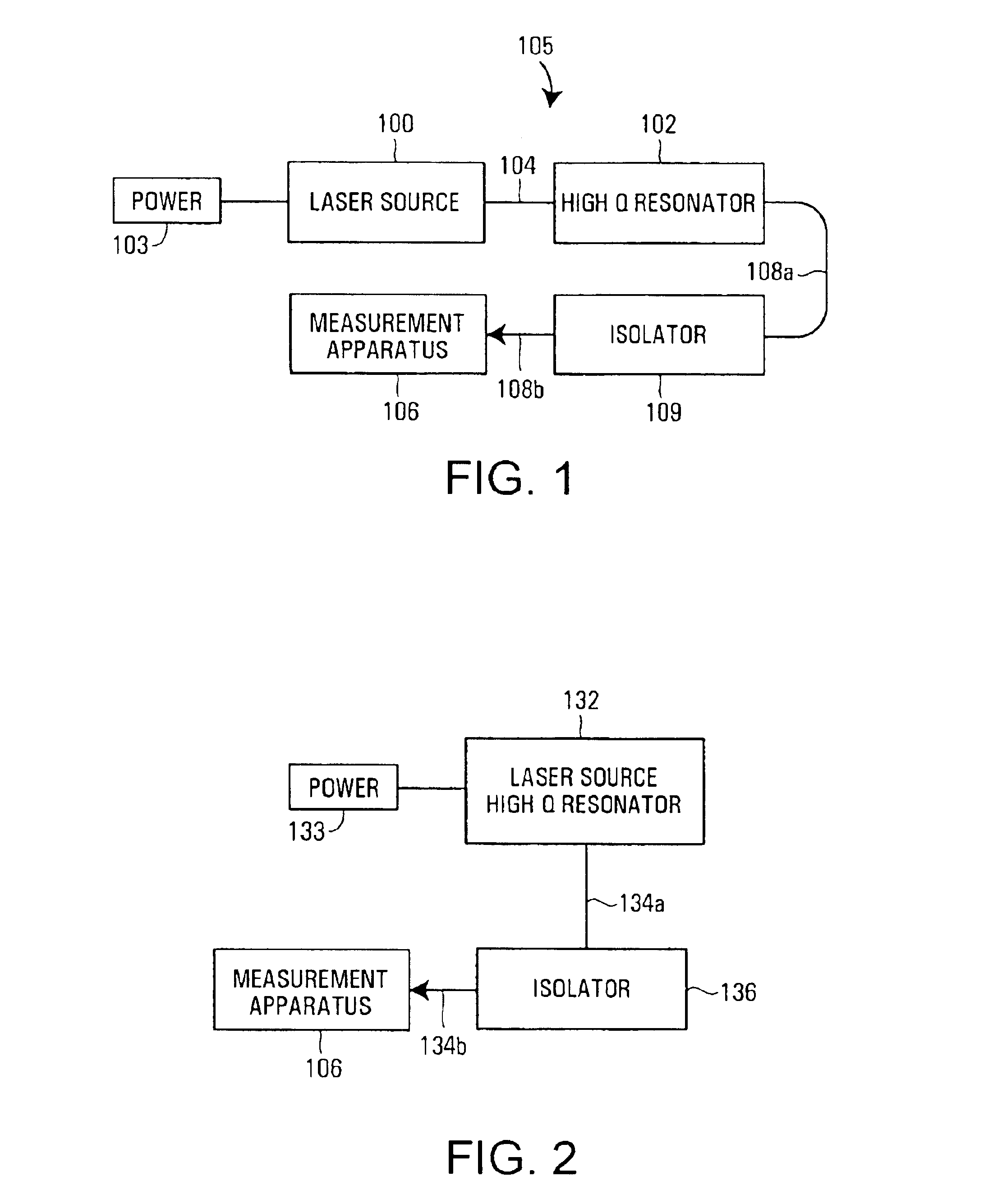
[0053]In some embodiments, a high Q optical resonator produces the laser signal with a frequency dependant upon the measurable parameter. The high Q resonator can be internal or external to the laser. The devices have lower power consumption and improved accuracy over the state of the art. The devices may be used to measure changes in a measurable parameter or they may be used to mak...


PUM


Abstract

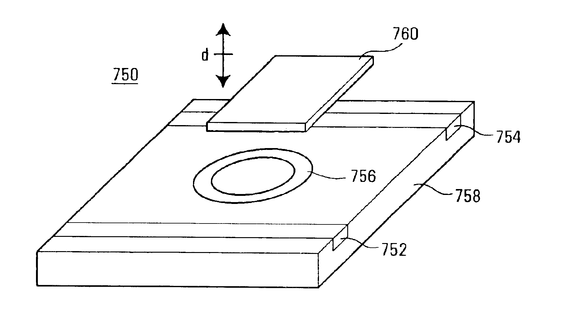
A tunable filter having a resonator with a resonant frequency dependent upon a variable gap is provided. The variable gap may be controllably altered by use of an actuator. The resonator is a high Q resonator that may be formed by a ring resonator, microsphere, microdisc, or other high Q optical structures. Actuation is preferably achieved through an electrostatic actuator that moves a dielectric plate relative to the resonator in response to measured values of gap and temperature.

Description

FIELD OF THE INVENTION[0001]The present disclosure relates generally to optical filters and more specifically to tunable optical filters.BACKGROUND OF THE PRIOR ART[0002]Optical communication systems like networking and telecommunications systems rely upon laser signals for information transmission. Whether via continuous wave or pulsed mode signaling, point-to-point data transfer is achieved through the creation, modulation, amplification, and transmission of laser signals. Data carrying laser signals pass through amplifiers, switches, filters, oscillators, and other optical components that make-up the optical communication system.[0003]To be useful in transferring numerous data packets simultaneously, originating laser signals must have narrow bandwidth. Generally, any suitable laser source produces an output having a relatively narrow bandwidth, a bandwidth in part determined by the lasing medium gain profile and in part by the properties of the cavity within which the lasing med...

Claims


Application Information

Patent Timeline
Patent Type & Authority Patents(United States)
IPC IPC(8): G02B6/26G02B6/02G02B6/12G02B6/122H01S5/14
CPCB82Y20/00G02B6/1225G02B6/12007G02B6/02052
Inventor FRICK, ROGER L.
Owner ROSEMOUNT INC
Learn More