Thermally-assisted magnetic recording head, method of manufacturing the same, and thermally-assisted magnetic recording apparatus

a technology of magnetic recording head and magnetic recording apparatus, which is applied in the field of thermally assisted magnetic recording head and thermally assisted magnetic recording apparatus, to achieve the effects of enhancing ku, efficient and stable recording, and ensuring durability to thermal disturban

Inactive Publication Date: 2006-05-09
KK TOSHIBA
View PDF30 Cites 64 Cited by
  • Summary
  • Abstract
  • Description
  • Claims
  • Application Information

AI Technical Summary

Benefits of technology

[0010]Significant points in exemplifying this basic concept include (1) the recording magnetic field should have been applied, and the recording should have been completed before the medium is cooled while it undergoes a heating treatment or immediately after the treatment; (2) after the recording is completed, recording magnetization should be prevented from being reversed because of adverse effects of thermal disturbance till the medium is fully cooled; and (3) only a minute region as wide as the recording magnetic pole should be selectively heated without destruction of magnetization transition due to the thermal disturbance caused by undesirably heating adjacent tracks.
[0088]Moreover, even when the medium is moved at high speed, the thermally-assisted magnetic recording is ensured, and the super enhanced density, extraordinarily high-speed thermally-assisted magnetic recording apparatus can be implemented, and this is industrially remarkably profitable.

Problems solved by technology

When a uniformly magnetized film or a non-crystalline magnetic film is used, this type of the medium is disadvantageous in comparison with the poly-particle medium in that the record density is determined depending upon a thickness of a magnetic domain wall (10 to 20 nm), and if the magnetic domain wall is to be displaced, a speed of data transfer is determined depending upon a speed of the displacement of the domain wall (several tens meters / s); meanwhile, a volume V of the magnetized particle is regarded as being infinite, and therefore, there is no need of allowing for the adverse effects of the thermal disturbance.

Method used


Image

  • Thermally-assisted magnetic recording head, method of manufacturing the same, and thermally-assisted magnetic recording apparatus
  • Thermally-assisted magnetic recording head, method of manufacturing the same, and thermally-assisted magnetic recording apparatus
  • Thermally-assisted magnetic recording head, method of manufacturing the same, and thermally-assisted magnetic recording apparatus

Examples


embodiment 1

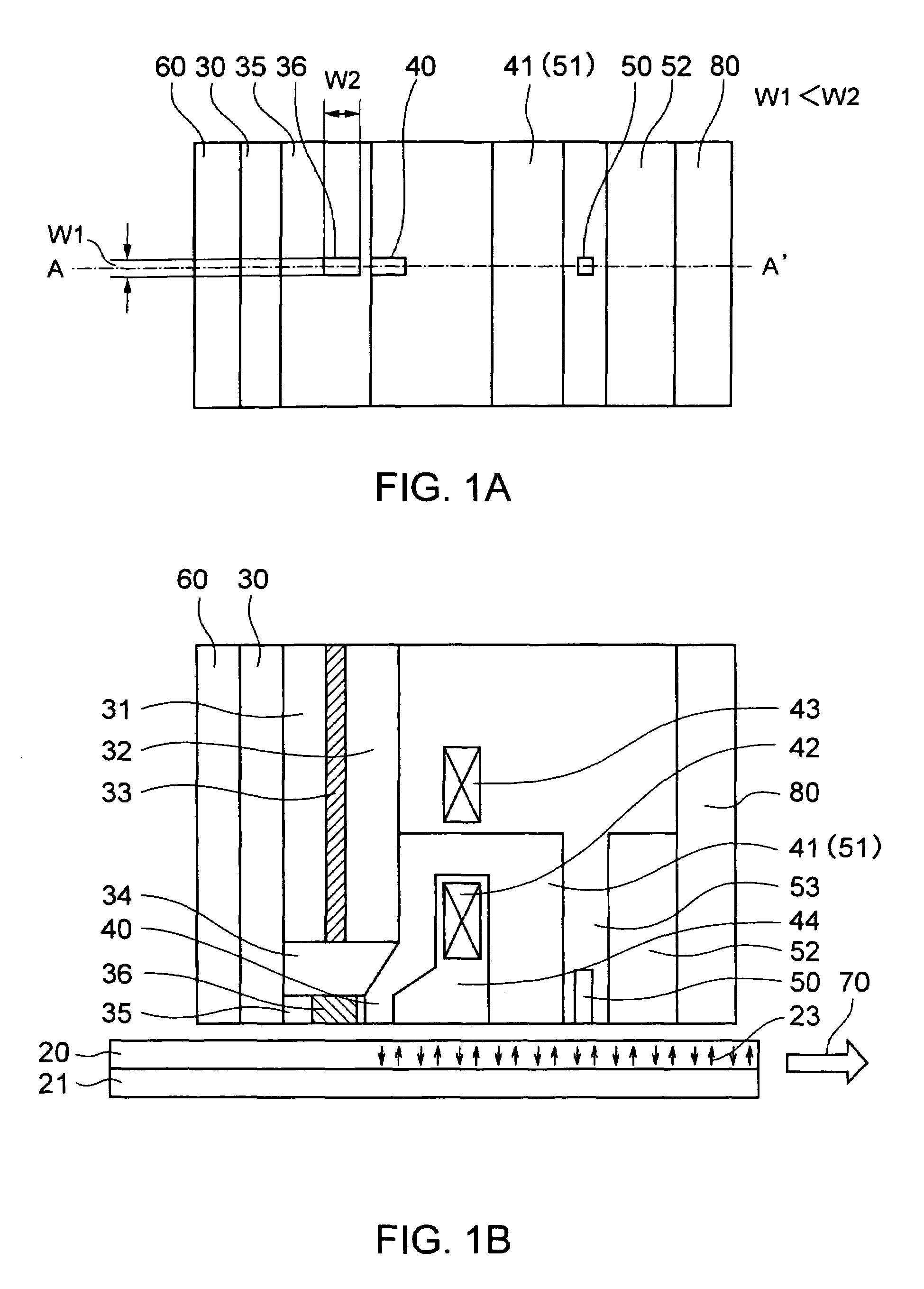
[0127]FIGS. 1A and 1B are schematic diagrams showing a thermally-assisted magnetic recording apparatus of a first preferred embodiment according to the present invention. FIG. 1A is a plan view illustrating a recording / reproducing head seen from a recording medium while FIG. 1B is a sectional view showing the recording / reproducing head including the recording medium, taken along the line A–A′ corresponding to a direction of recording tracks.

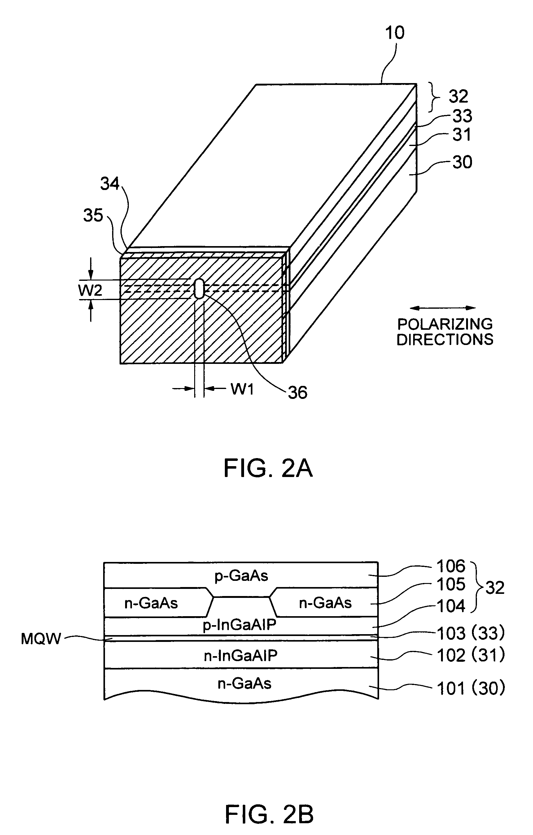
[0128]In the figures, reference numerals 20 to 22 denote primary portions of the recording medium while the remaining reference numerals all denote primary components of the recording / reproducing head. The primary components of the head include a light emitting device comprised of elements designated by reference numerals 30 to 36, a magnetic recording device comprised of elements designated by reference numerals 40 to 44, a magnetic reproducing device comprised of elements designated by reference numerals 50 to 53, and a protective coating desig...

embodiment 2

[0178]A second preferred embodiment according to the present invention will now be described.

[0179]FIG. 18 is a sectional schematic view showing a configuration of a thermally-assisted magnetic recording apparatus of this preferred embodiment. FIG. 19 is a perspective conceptual view showing a configuration of a light emitting device used in this embodiment. FIG. 18 is a side sectional view of the apparatus including a medium, extending in a direction of tracks and taken along the line A–A′ in FIG. 19 (a direction of the line corresponds to a direction of the recording tracks). In these figures, like reference numerals denote parts similar to those in FIGS. 1 and 2, and details of them are omitted.

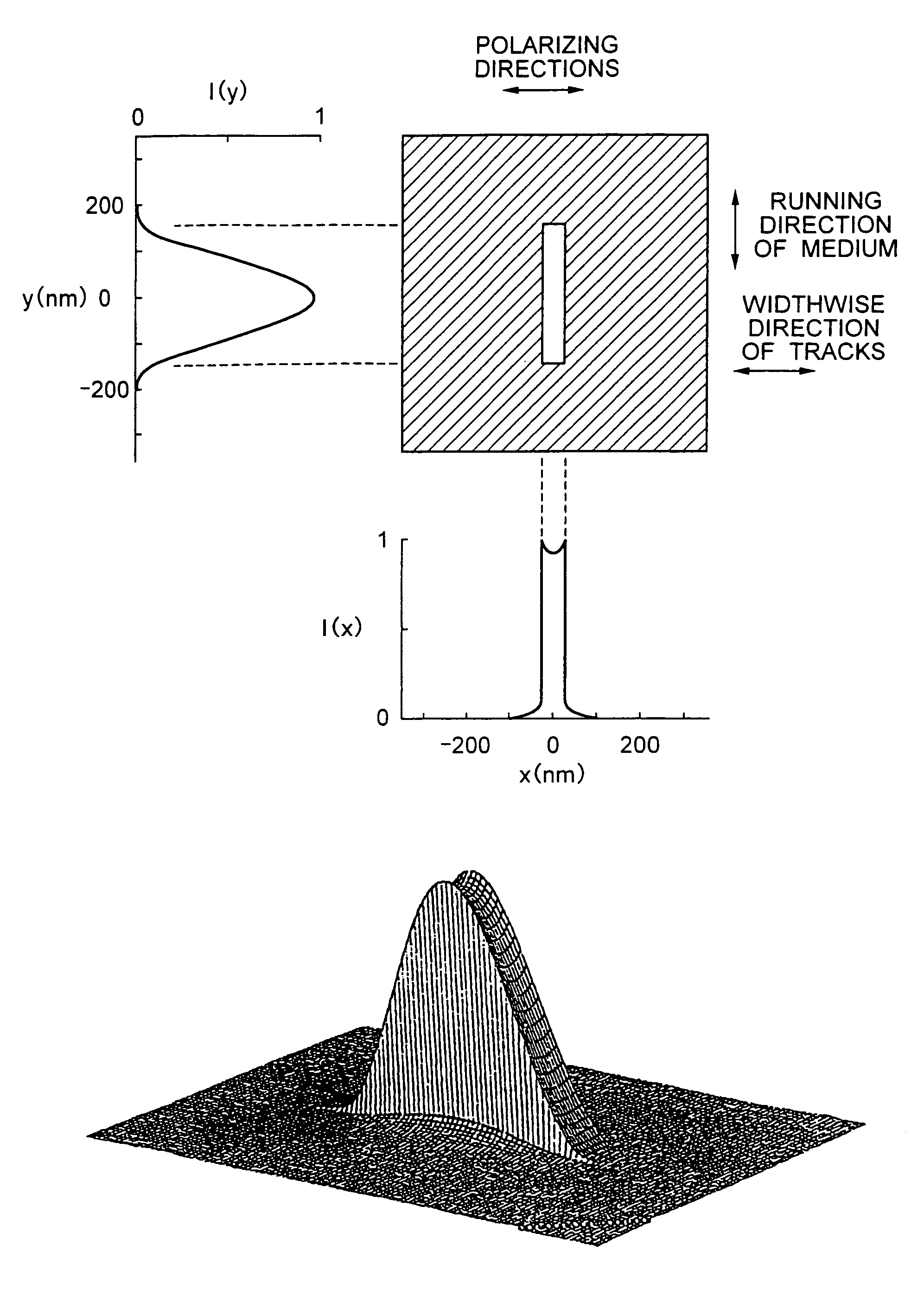
[0180]Reference numerals 20, 33, 34, 35, and 36 designate a semiconductor laser device, an active layer, an insulating film, a light absorbing film, and an aperture created in the light absorbing film 35, respectively. A direction of polarization of the laser is perpendicular to a junction...

embodiment 3

[0184]A third preferred embodiment of the present invention will be described.

[0185]FIG. 20 is a schematic conceptual diagram showing the thermally-assisted magnetic recording apparatus of this embodiment. FIG. 21 is a perspective conceptual diagram showing an arrangement of a light emitting device used in this embodiment. FIG. 20 is a side sectional view of the apparatus including the medium in a direction of the tracks, taken along the line A–A′ in FIG. 21 (a direction of the line corresponds to a direction of the tracks). Like reference numerals denote similar parts to those in FIGS. 1 to 19, and details thereof are omitted.

[0186]Although the aforementioned first and second preferred embodiments include an edge-emitting laser devices which are located close to a leading section of an ordinary multi-layered thin film magnetic head, the present invention is suitable for an application in which a vertical cavity surface emitting laser device which is mounted on a planar thin film ma...


PUM


Abstract

A thermally-assisted magnetic recording head and a magnetic recording apparatus having the magnetic recording head built in are disclosed. The magnetic recording head is capable of recording magnetic information by heating a recording unit of a recording medium and raising its temperature to reduce magnetic coercive force and then applying recording magnetic field to the recording unit having the reduced coercive force. The magnetic recording head has a light absorbing film having an aperture, a laser device emitting and directing light through the aperture to the recording medium to head the recording unit and raise its temperature, and a recording magnetic pole for applying the recording magnetic field to the recording unit. In the aperture, an aperture width W1 is along a polarizing direction of the light emitted from the laser device while an aperture width W2 is approximately perpendicular to the polarizing direction of the aperture width W1, and the aperture width W1 is shorter than the aperture width W2. The heating source such as a laser device recedes from the medium to provide a unique configuration where a tip of the recording magnetic pole protrudes ahead of the heating source, and hence, heating beam and the recording magnetic pole can be located close to each other without losing sufficient energy density to heat the medium.

Description

BACKGROUND OF THE INVENTION[0001]The present invention relates to a thermally-assisted magnetic recording head and a thermally-assisted magnetic recording apparatus, and more particularly, it relates to newly improved thermally-assisted magnetic recording head and thermally-assisted magnetic recording apparatus in which light irradiation is used to heat a magnetic recording medium and raise a temperature thereof to carry out magnetic recording, so that the very high density magnetic recording can be attained.[0002]Magnetic recording apparatuses which magnetically record and reproduce information have been developed as large-capacity, high-speed, and inexpensive information storing means. Especially, recent advancement of hard disk drives (HDD) is remarkable to such an extent that recording density of finished commercial products reaches 10 Gb / in2 (Giga bytes per square inches) or over while an internal data transfer speed is 100 Mbps (Mega bytes per second) or above, and a price in ...

Claims


Application Information

Patent Timeline
IPC IPC(8): G11B11/105G11B15/64G11B5/02G11B5/00G11B5/127G11B9/00G11B9/10G11B13/04
CPCB82Y10/00G11B5/00G11B5/127G11B9/10G11B2005/0021G11B13/045G11B2005/0002G11B2005/0005G11B9/1409G11B5/6088G11B5/314
Inventor AKIYAMA, JUNICHIICHIHARA, KATSUTAROHATAKOSHI, GENICHI
Owner KK TOSHIBA
Why Eureka
Try Eureka