
Transducer in-situ testing apparatus and method

a technology of in-situ testing and transducers, applied in the direction of interia force acceleration measurement, static/dynamic balance measurement, instruments, etc., can solve the problems of failure or degradation, other related properties that are difficult to ascertain without specific testing equipment and without taking, and the amplifier is useless and needs to be replaced immediately, etc., to achieve the effect of disabling the amplifier

Inactive Publication Date: 2006-05-09
OCEANA SENSOR TECH
View PDF11 Cites 29 Cited by
  • Summary
  • Abstract
  • Description
  • Claims
  • Application Information

AI Technical Summary

Benefits of technology

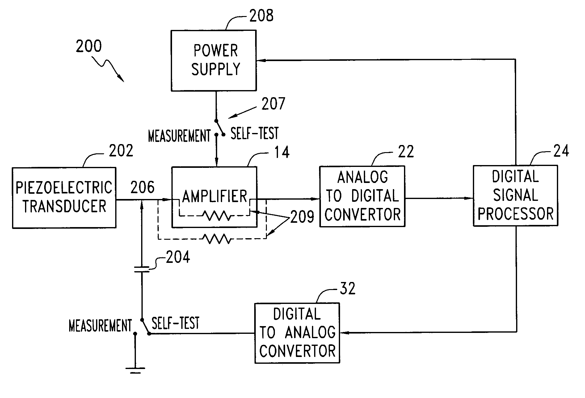
[0011]The present invention is directed to an apparatus and method for a measurement system for the testing of transducers, and more particularly to the testing of piezoelectric transducers. The measurement system includes a transducer, a feedback amplifier coupled to the transducer and a signal processing circuit coupled to the output of the amplifier. The method of testing the transducer includes coupling the test signal to the transducer, disabling the amplifier, and measuring the response of the transducer to the test signal with the test processing circuit. The circuit itself used for performing this method includes a piezoelectric transducer, an amplifier, including a feed-back circuit coupled to the amplifier for amplifying the output of the transducer, a power source coupled to the amplifier, a signal source generating a test signal having a frequency spectrum at least overlapping the self resonant frequency of the transducer coupled to the transducer, and a switch coupled to the amplifier capable of disabling the amplifier.

Problems solved by technology

For instance, if there is a failure of the bond between the structure being monitored and the piezoelectric accelerometer, it would be important for an operator to know this as soon as possible since any data collected subsequent to the failure would be unreliable.
If there is any internal mechanical failure of the piezoelectric accelerometer, the device is useless and needs to be replaced immediately.
In the past, failure or degradation and other related properties have been difficult to ascertain without specific testing equipment and without taking apart the machine on which the transducer was installed.
With the advent of microcircuitry and embedded sensors, this is extremely expensive and difficult to accomplish without destroying the transducer and possibly other parts of the monitoring device as well as the body being monitored.

Method used


Image

  • Transducer in-situ testing apparatus and method
  • Transducer in-situ testing apparatus and method
  • Transducer in-situ testing apparatus and method

Examples


Embodiment Construction

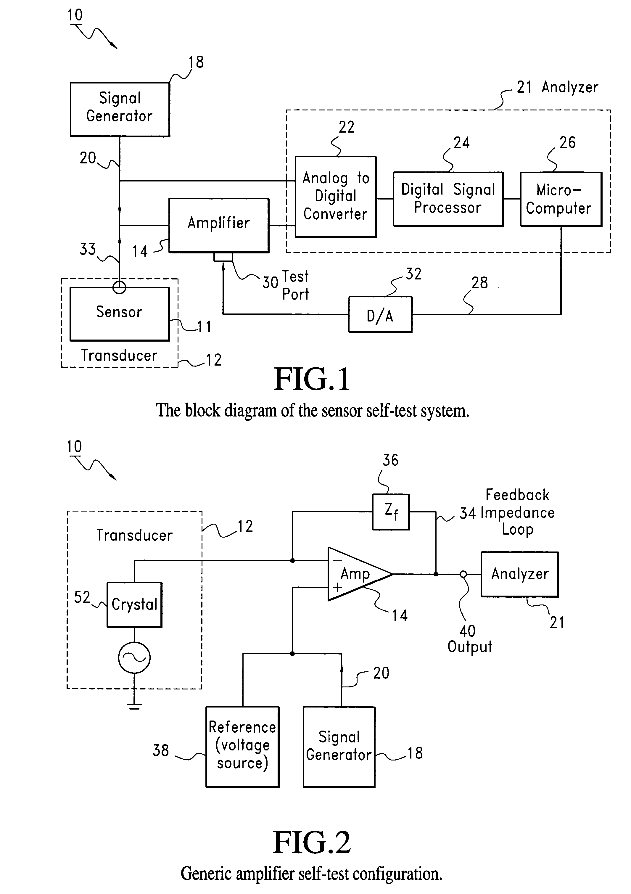
[0045]This invention provides a method and an apparatus for the in situ measurement of the electrical output impedance of any transducer allowing the transducer to have an internal self-testing circuit capable of implementing self-testing. In many cases the self-testing apparatus can be simply retrofitted to an existing transducer circuit. A block diagram of the self-test measurement system is shown in FIG. 1. The self-testing measurement system, also known as a self-testing circuit 10 and method can be conveniently implemented with an “intelligent” sensor shown in FIG. 1. The self-testing circuit 10 includes a sensor 11 with a circuit, called a transducer 12, an amplifier 14 sometimes called a preamplifier 14, a signal generator 18 that can generate a test signal 20 traveling in the direction of the arrow. The self-testing circuit 10 also has an analyzer 21 that can include an analog to digital converter 22, a digital signal processor 24 and a microcomputer 26. The microcomputer co...


PUM

PropertyMeasurementUnit
capacitanceaaaaaaaaaa
frequencyaaaaaaaaaa
currentaaaaaaaaaa

Abstract

The present invention is directed to an apparatus and method for a measurement system for the testing of transducers, and more particularly to the testing of piezoelectric transducers. The measurement system includes a transducer, a feedback amplifier coupled to the transducer and a signal processing circuit coupled to the output of the amplifier. The method of testing the transducer includes coupling the test signal to the transducer, disabling the amplifier, and measuring the response of the transducer to the test signal with the test processing circuit. The circuit itself used for performing this method includes a piezoelectric transducer, an amplifier, including a feed-back circuit coupled to the amplifier for amplifying the output of the transducer, a power source coupled to the amplifier, a signal source generating a test signal having a frequency spectrum at least overlapping the self resonant frequency of the transducer coupled to the transducer, and a switch coupled to the amplifier capable of disabling the amplifier.

Description

CROSS-REFERENCE TO RELATED APPLICATIONS[0001]This application is a continuation-in-part of application Ser. No. 10 / 131,673, filed Apr. 24, 2002 now U.S. Pat. No. 6,698,269 entitled TRANSDUCER IN-SITU TESTING APPARATUS AND METHOD, and Ser. No. 10 / 131,673 claims the benefit of U.S. Provisional Application No. 60 / 286,932, filed Apr. 27, 2001 entitled METHOD AND APPARATUS FOR AUTOMATED IN-SITU TESTING OF SENSORS INCLUDING PIEZOELECTRIC ACCELEROMETERS.FIELD OF INVENTION[0002]This invention relates to an apparatus and method for in-situ testing of transducers, and more particularly to the testing of piezoelectric transducers including piezoelectric accelerometers.BACKGROUND[0003]Transducers are widely used in measurement systems. The term transducer refers either to a sensor or an actuator. “Sensor” normally refers to a device that detects a change in a physical property due to a physical stimulus and turns that stimulus into a signal, which can be measured or recorded. “Actuator” refers ...

Claims


Application Information

Patent Timeline
Patent Type & Authority Patents(United States)
IPC IPC(8): G01R31/08G01P21/00G01R29/22H03F1/14G01D3/08G01H3/00G01L9/08G01L25/00G01P15/09
CPCG01D3/08G01H3/005G01P21/00G01L25/00G01P15/09G01L9/08G01S7/52004
Inventor LALLY, RICHARD W.KENNAMER, DONALD E.BABER, ISAAK
Owner OCEANA SENSOR TECH
Learn More