
Wind turbine

a wind turbine and wind power technology, applied in the direction of synchronous motors, electric generator control, climate sustainability, etc., can solve the problems of increasing the stress and wear and tear of the fixed speed turbine, reducing the efficiency of the speed increaser gearbox, and increasing the number of deficiencies of fixed speed wind turbines, so as to reduce the cost per unit of power generation, improve efficiency, and slow speed power generation

Inactive Publication Date: 2006-05-09
MARIAH POWER
View PDF25 Cites 232 Cited by
  • Summary
  • Abstract
  • Description
  • Claims
  • Application Information

AI Technical Summary

Benefits of technology

[0011]Accordingly, the invention provides a wind turbine with increased efficiency and substantially lower costs per unit power generation. The wind turbine allows slow speed power generation with reduced weight, quiet operation, near indefinite maintenance-free operation and the potential for modular construction.

Problems solved by technology

Unfortunately, fixed speed wind turbines have numerous deficiencies.
Operation at fixed speed puts increased stress and wear and tear on the turbine.
The speed increaser gearbox reduces efficiency.
The speed increaser gearbox is also the largest failure component of wind turbine operation and requires regular maintenance.
Fixed speed operation is also very noisy especially in low wind when it is most noticeable.
Although easily connected with utility power, the asynchronous generator provides low quality power with a low power factor.
Induction generators also suffer from low efficiency and they do not generate power unless connected to grid power, eliminating the possibility of stand-alone generation.
The biggest challenge is the reduction of the cost per unit power generation capability.
Despite the development of variable speed wind turbines employing large synchronous ring generators, wind turbines continue to suffer from deficiencies.
Most importantly, wind turbines with synchronous ring generators are very costly.
This is due to both the use of a large amount of costly permanent magnets and / or electrical laminations and also to the very labor-intensive fabrication and assembly processes.
Processes such as punching stacking, grinding, winding, insulating, coil inserting, coil connection and high tolerance alignment increase costs.
On top of this, costly close tolerance components are required to achieve the required small magnetic airgaps for achieving efficient operation.
Other problems with current synchronous ring wind turbine generators include the need for extremely large and rigid generator structure and also assembly tooling to deal with the tremendous magnetic attraction forces between the rotor and stator portions.
As a result of the massive structure, generators therefore become excessively heavy, making them more difficult to transport and to install.
Wound field synchronous ring generators can eliminate the problem of rotor to stator attraction during assembly, but not in operation when field current is applied to the field coils for power generation.
In addition, wound field generators are both more costly and achieve lower performance.
Currently available synchronous ring generators suffer from less than optimal efficiency and provide limited power generation capability in reduced wind speeds.
In many cases, substantial cooling systems are also required to cool the generator and remove energy that is wasted as heat.

Method used


Image

  • Wind turbine
  • Wind turbine
  • Wind turbine

Examples


Embodiment Construction

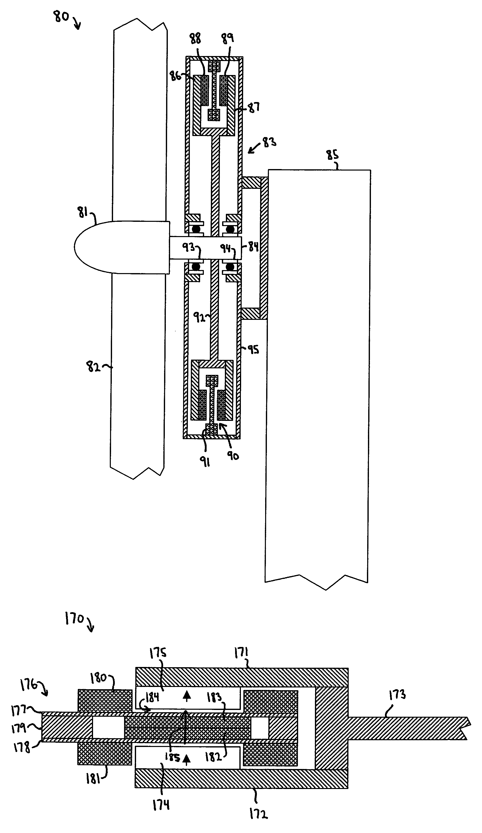
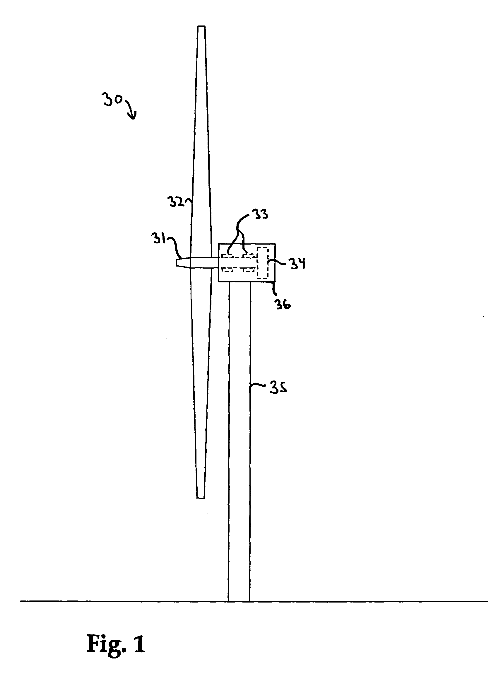
[0093]Turning to the drawings wherein like characters designate identical or corresponding parts, a wind turbine 30, shown in FIG. 1. includes a turbine rotor 31 having multiple blades 32 that are driven by the wind. The turbine rotor 31 is supported a bearing system 33 and drives an electrical generator 34. The generator 34 is housed in a nacelle 36 on top of a support pole 35. Other configurations for a driving the generator by wind energy could also be used in accordance with the invention. For instance, a gearbox could be utilized, but this typically reduces efficiency and reliability. In most cases, it is preferable to eliminate the gearbox for new wind turbines by using direct-drive generators in accordance with the invention, and achieving full power and voltage at the rotational speed of the turbine rotor.

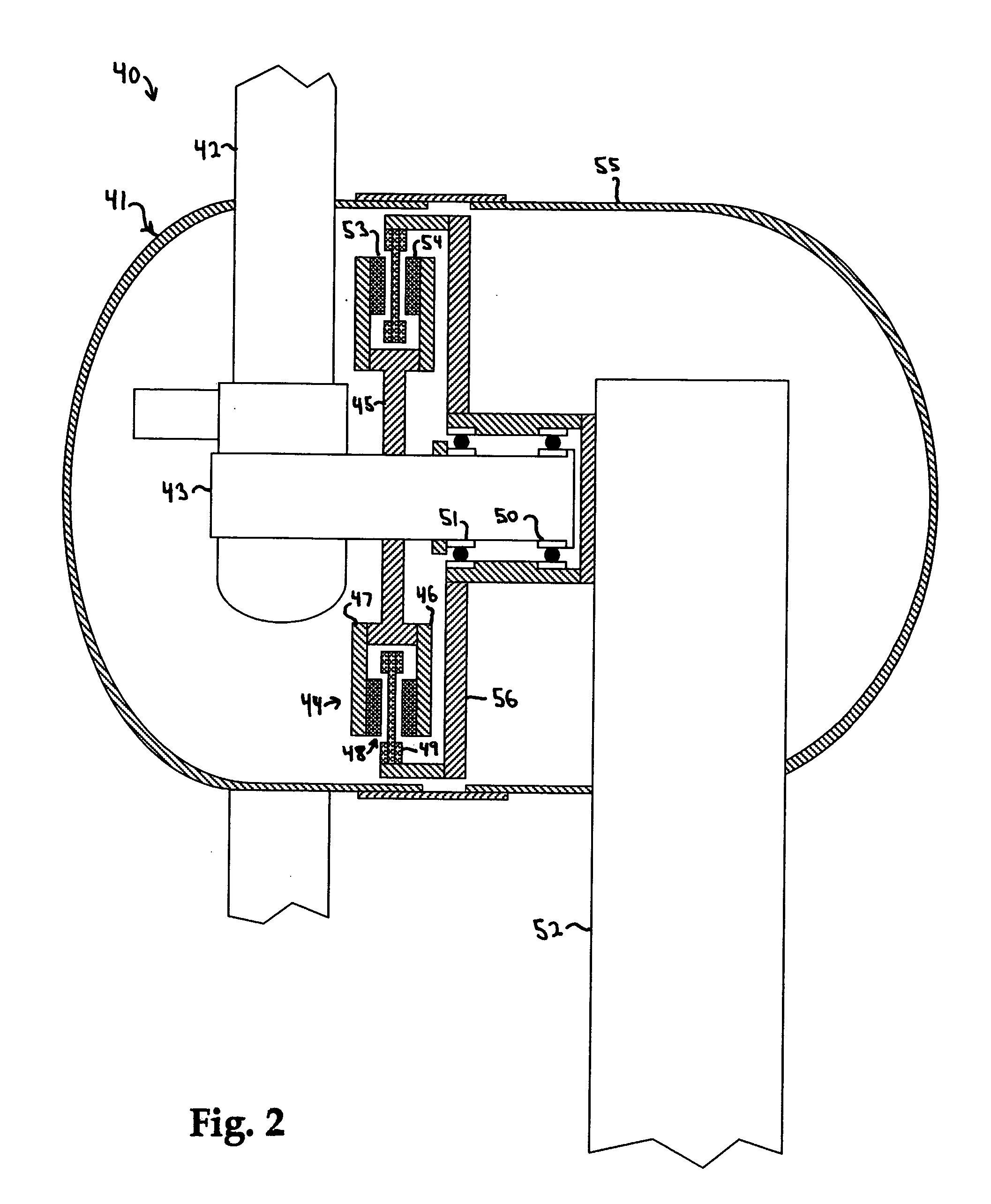
[0094]A wind turbine 40 is shown in FIG. 2 having a turbine rotor 41 with two or more blades 42 for converting wind energy into rotational energy. The turbine rotor 41 is a...


PUM


Abstract

A wind turbine for generating electrical power from wind energy includes a turbine rotor mounted for rotation in wind, and having multiple blades for converting energy in the wind into rotational energy. A generator is coupled with said turbine rotor such that said turbine rotor drives said generator. The generator has a stationary air core armature that is located in a magnetic airgap between two generator rotor portions. The generator rotor portions have circumferential arrays of multiple alternating polarity permanent magnets attached to ferromagnetic back irons such that the permanent magnets drive magnetic flux back and forth between each rotor portion and through the stationary air core armature. The stationary air core armature has multiple phase windings of multiple individually insulated strand conductor wire that is wound with two separate portions including an active length portion and an end turn portion. The end turn portion is located outside the magnetic airgap and traverses predominately circumferentially, and the active length portion is located in the magnetic airgap and traverses predominately non-circumferentially and perpendicular to the direction of the magnetic airgap. The end turn portion has a thickness that is greater than the thickness of said active length portion in the direction of said magnetic airgap. AC voltage is induced in the multiple phase windings as the turbine rotor rotates.

Description

[0001]This is related to U.S. Provisional Application No. 60 / 407,551 filed on Aug. 30, 2002 and entitled “Wind Turbine”.[0002]This invention pertains to wind turbines, and more particularly to a permanent magnet excited wind turbine having a specialized generator construction that provides increased efficiency and substantially lower costs per power generation. The wind turbine is compatible for use in low speed direct drive wind turbines and can provide reduced weight, quiet operation, near indefinite maintenance-free operation and the potential for modular construction allowing easier transportation.BACKGROUND OF THE INVENTION[0003]Use of wind turbines for generating electrical power is currently increasing while recent technical advances along with economics and legislation have made the use of wind turbines a viable generation alternative. Wind turbines range from small sizes of 1–50 kW for power generation for homes, farms and small business up to 5 MW in large scale off shore ...

Claims


Application Information

Patent Timeline
IPC IPC(8): H02P9/04F03B15/06F03D7/02F03D9/00F16C39/06H02K3/47H02K7/02H02K7/09H02K7/18H02K9/06H02K19/10H02K29/08
CPCF03D9/002H02K7/1838H02K19/103F03D11/0008F05B2220/7066F05B2220/7068H02K3/47H02K7/02H02K7/025H02K7/09H02K9/06H02K29/08Y02B10/30Y02E10/722Y02E10/725F03D9/25F03D80/70F16C2360/31Y02E10/72
Inventor GABRYS, CHRISTOPHER W.
Owner MARIAH POWER
Learn More