
Fiber extended, semiconductor laser

a fiber and laser technology, applied in the field of lasers, to achieve the effect of low cost structur

Inactive Publication Date: 2006-05-02
THORNTON ROBERT L
View PDF18 Cites 10 Cited by
  • Summary
  • Abstract
  • Description
  • Claims
  • Application Information

AI Technical Summary

Benefits of technology

[0006]Coupling of a VCSEL to an appropriate optical fiber to produce an extended cavity provides the design flexibility to address all of these enhanced applications, while maintaining the low cost structure that makes the VCSEL a compelling solution.

Problems solved by technology

Third, it is desirable to establish laser operations at wavelengths for which VCSEL devices are currently not available, due to constraints of VCSEL materials availability and / or materials quality.

Method used


Image

  • Fiber extended, semiconductor laser
  • Fiber extended, semiconductor laser
  • Fiber extended, semiconductor laser

Examples


Embodiment Construction

[0025]In general, the present invention is directed to an approach that increases the single transverse mode output power from a vertical cavity, surface-emitting laser (VCSEL),permits the VCSEL to operate in multiple longitudinal modes, thus permitting the VCSEL to be used in mode-locked applications, and permits the VCSEL to emit efficiently at previously unavailable wavelengths.

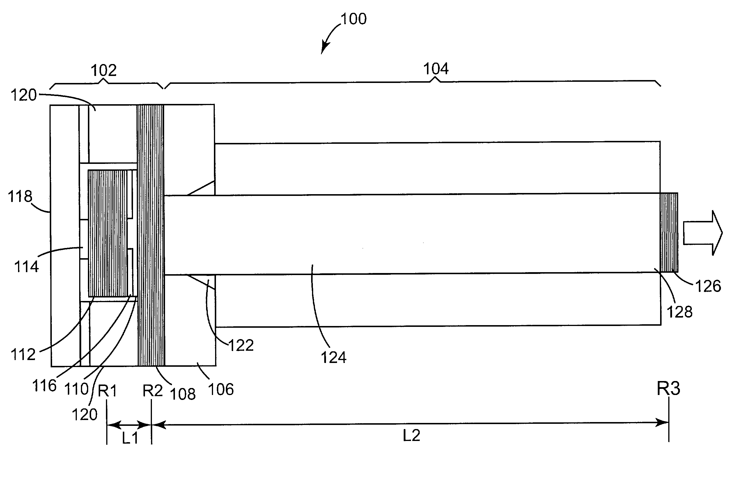
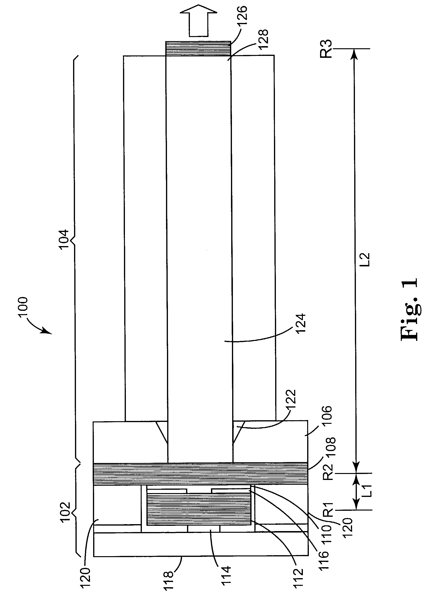
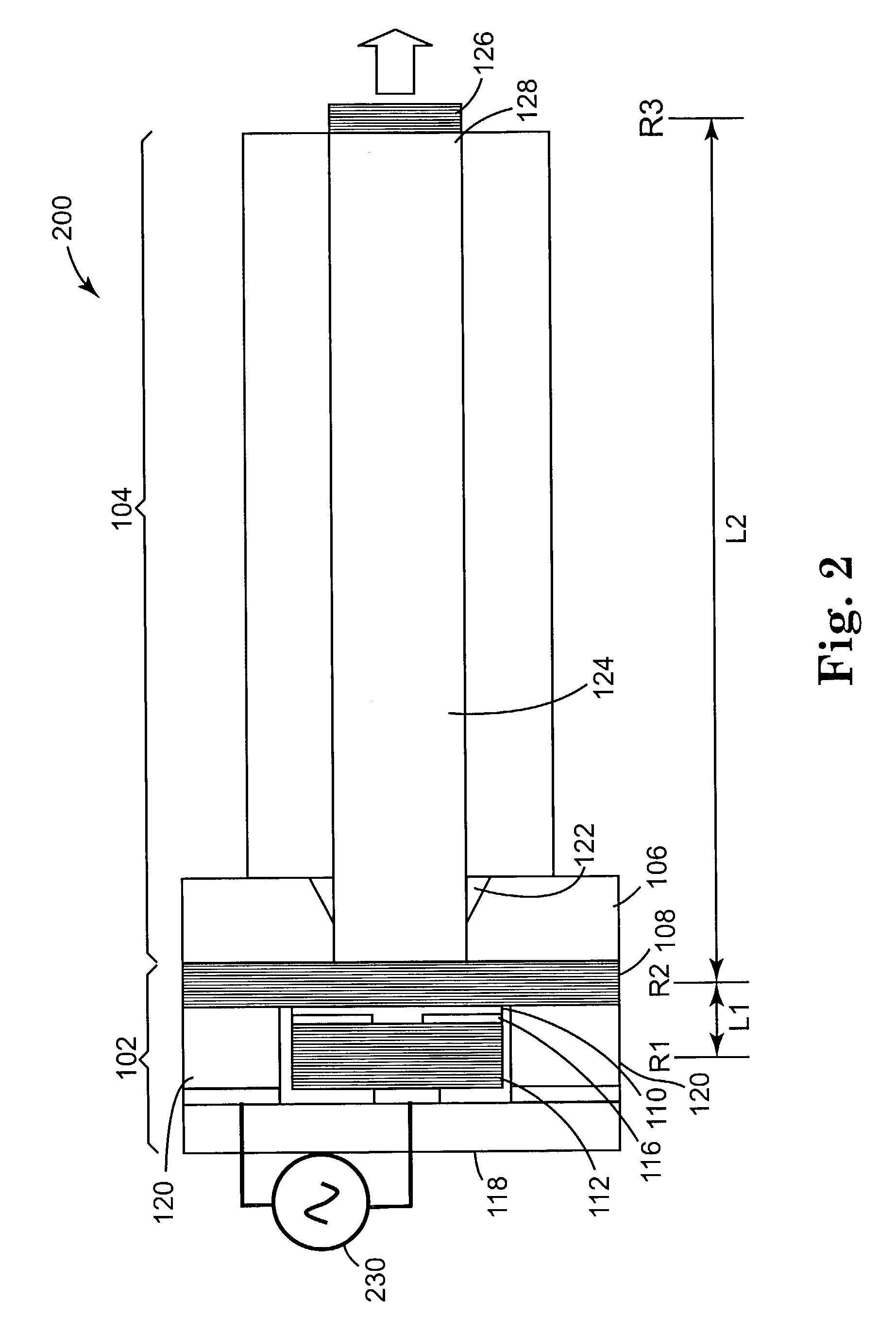
[0026]One particular embodiment of a fiber-extended VCSEL 100 according to the present invention is schematically illustrated in FIG. 1. The laser 100 comprises a vertical cavity portion 102 and an extended cavity portion 104. The vertical cavity portion 102 comprises a substrate 106 on which is formed a vertical cavity structure having an optional first mirror 108, a gain region 110, and a second mirror 112. The first mirror 108 is referred to hereafter as an intracavity reflector and the second mirror 112 is referred to as a high reflector. The intracavity reflector 108 and the high reflector 112 may be ...


PUM


Abstract

A semiconductor laser, such as a vertical cavity, surface emitting laser (VCSEL) is coupled to an optical fiber. The other end of the optical fiber has a reflector, so as to provide a fiber-extended cavity for the VCSEL. Such a construction is useful for providing modal stability to the VCSEL or for forming a mode-locked VCSEL. The optical fiber may be a graded index fiber. In such a case, the fiber length may be selected to have an integral number of quarter pitch lengths. The fiber may be doped with an excitable species and lies within a fiber laser cavity. A semiconductor laser may pump the fiber laser, yielding an emission wavelength beyond the scope of the conventional semiconductor laser.

Description

FIELD OF THE INVENTION[0001]The present invention is directed generally to lasers, and more particularly to semiconductor lasers such as vertical cavity, surface emitting semiconductor lasers (VCSELs).BACKGROUND[0002]Semiconductor lasers are key elements in the advancing performance of many systems, such as optical fiber communications, optical data storage, laser printing, full color displays, biochemical monitoring, optical clock generation and quantum key distribution.[0003]Vertical cavity, surface-emitting lasers (VCSELs) have become well established as low cost light sources for short distance data communications applications. There is extensive interest in extending the utility of VCSELs. However, barriers to further applications include efficient emission at targeted wavelengths and transverse modal properties. In particular, as a result of their very short cavities, VCSELs generally offer the benefit of single longitudinal mode emission, but at the expense of limited output ...

Claims


Application Information

Patent Timeline
Patent Type & Authority Patents(United States)
IPC IPC(8): H01S3/30H01SH01S3/067H01S3/094H01S3/0941H01S3/16H01S5/00H01S5/065H01S5/14H01S5/183
CPCH01S3/06716H01S3/09415H01S5/18305H01S5/146H01S3/094042H01S5/147H01S3/1616
Inventor THORNTON, ROBERT L.
Owner THORNTON ROBERT L
Learn More