
Luminous hands and display device including the same, particularly in a timepiece

a technology of display device and hand, which is applied in the field of hand or pointer, can solve the problems of inability to apply the same way as the aforementioned devices, difficulty in distributing light, and limited application of electric power consumption of these devices to date, and achieve the effect of large total surface area and uniform light distribution

Active Publication Date: 2006-05-02
THE SWATCH GRP RES & DEVELONMENT LTD
View PDF14 Cites 13 Cited by
  • Summary
  • Abstract
  • Description
  • Claims
  • Application Information

AI Technical Summary

Benefits of technology

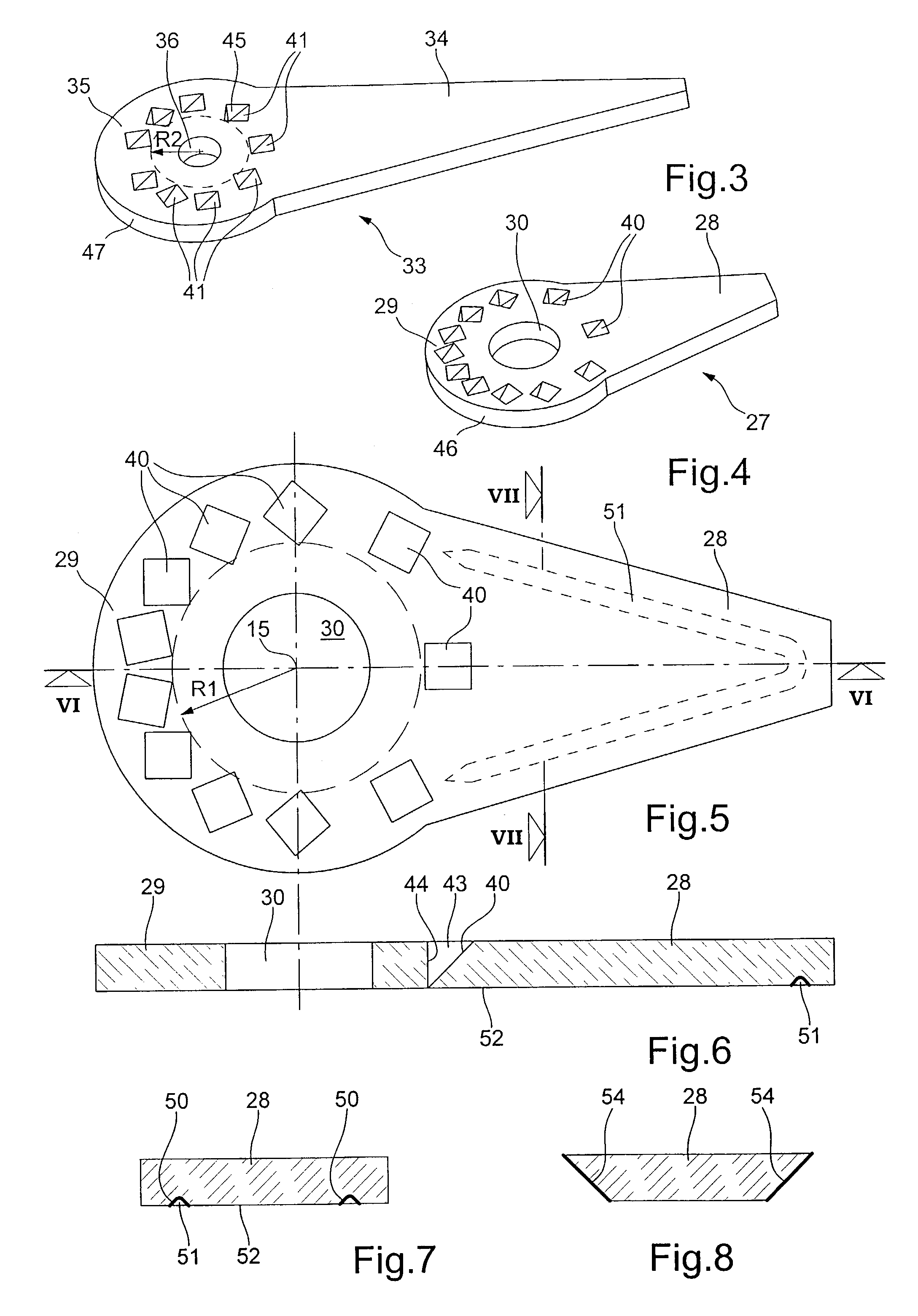
[0011]Owing to these arrangements, the reflectors can advantageously be distributed in the head of the hand not only in proximity to the body of the hand, but also in the parts of the head located at a distance from the body. Intercepting a part of the axial light flux in this way on different regions of the contour of the hand head offers several advantages. The reflectors can have a larger total surface area and thus intercept more light than a reflector disposed opposite the body of the hand as provided by Patent document No. WO 96 / 02810. When the light source is formed by two or more elements of small size, spaced out from each other around the rotational axis, suitable distribution of the reflectors provides a reflected light intensity which varies less, during the rotation of the hand, than with a single reflector located facing the body. Further, certain of the reflectors can advantageously be oriented differently, which allows the light to be directed in a preferred manner towards certain regions of the hand, either to illuminate such regions more particularly, or to obtain sufficiently uniform distribution of the light taking account of the shape of the hand.

Problems solved by technology

However, the electric power consumption of these devices has limited their applications to date.
The idea of internally illuminating the hands of a timepiece for the same purpose is already an old one, but cannot be put into practice in the same way as in the aforementioned devices, particularly because of the coaxial arrangement of the hour, minute and possibly second hands, and the superposition of the circular heads of the hands.
This thus results in particular difficulties for distributing the light.
Thus, most of the light emitted by the lamps is lost because it passes to the side of the mirrors.
Moreover, a construction of this kind with hollow hands is evidently too voluminous to be able to be applied to a watch.
This system has the drawback of requiring rotating electric contacts which take a lot of space and are unreliable in the long term.
However, this construction has not had any commercial success, probably because of unsatisfactory light distribution in the hands.

Method used


Image

  • Luminous hands and display device including the same, particularly in a timepiece
  • Luminous hands and display device including the same, particularly in a timepiece
  • Luminous hands and display device including the same, particularly in a timepiece

Examples


Embodiment Construction

[0022]The watch movement can be of any type. If it is electronic, it can be mounted either on the bottom face of printed circuit board 20, or on another board located underneath.

[0023]Hands 11 and 12 are intended to be illuminated internally by light source 21, to facilitate reading the time and particular to make this possible in the dark. There is no illumination of the dial in the example shown here, but this can be provided, as will be explained hereinafter.

[0024]In FIG. 2, hour hand 11 is shown in dotted lines because it is masked by minute hand 12. In FIGS. 3 to 6, the central bush of each hand has been omitted in order to show only the transparent part of the hand.

[0025]Hour hand 11 includes a central metal bush 26 and a part 27 (FIG. 4) made of transparent material that forms an elongated body 28 and a circular head 29 of the hand, head 29 having a central hole 30 in which bush 26 is fixed. Part 27 may advantageously be a moulded synthetic part, for example made of PMMA, man...


PUM


Abstract

There is provided a type of luminous hand including a part made of moulded transparent material that forms a circular head (28, 35) and a body (28, 34) of a hand. In order to direct a portion of a light beam parallel to the axis (15) of the hand towards the interior of the body, the head includes a plurality of reflectors (40, 41) distributed around the axis and formed by dihedron shaped hollows. This improves the intensity and uniformity of the light in the hand body. Inclined light-diffusing surfaces, covered with a light coloured paint, are arranged on the bottom face of the hand. In a display device with several coaxial hands (11,12) such as that of a watch, the reflectors of the superposed heads (29, 35) of the hands are located at respective distances from the axis which are different from one hand to another, such that they never completely cover each other. The light source preferably includes three light-emitting diodes (23) located under the dial (10). A cylindrical light guide (18) is placed between the source and the heads of the hands, in the central opening in the dial.

Description

BACKGROUND OF THE INVENTION[0001]The present invention concerns a hand or pointer comprising a part made of transparent material and capable of being illuminated so that the hand becomes luminous and visible even in the dark, in particular in an analogue display device such as a timepiece.[0002]The invention also concerns an analogue display device for a timepiece, including such hands. The invention further concerns a watch including such a display device.[0003]Currently, it is common to use a hand made of transparent coloured material which is illuminated internally so that it appears to be luminous, in particular to facilitate night reading of an analogue indicator such as the speedometer of an automobile. One can find for example in Patent publications Nos. WO 96 / 02810, U.S. Pat. No. 5,546,888 and DE 38 17 874, the description of devices in which a light beam, produced by a fixed source, axially penetrates a transparent rotating hub of the single hand and reaches a reflection su...

Claims


Application Information

Patent Timeline
Patent Type & Authority Patents(United States)
IPC IPC(8): G04B19/30G01D11/28G01D13/22G04B19/06G04B19/04G04B19/32
CPCG04B19/32G04B19/042
Inventor FERRI, YVANBORN, JEAN-JACQUESVIENNET, RENERICCHIUTO, JOSEPH
Owner THE SWATCH GRP RES & DEVELONMENT LTD
Learn More