
Bumper airbag with multiple chambers

a bumper airbag and airbag technology, applied in bumpers, pedestrian/occupant safety arrangements, tractors, etc., can solve the problems of new problems in the collision area of vehicles, and achieve the effect of reducing the amount of momentum transferred, reducing the energy transmitted, and reducing the amount of energy transmitted

Inactive Publication Date: 2006-05-02
FORD GLOBAL TECH LLC
View PDF25 Cites 41 Cited by
  • Summary
  • Abstract
  • Description
  • Claims
  • Application Information

AI Technical Summary

Benefits of technology

[0013]An advantage of the present invention is that it reduces the energy transmitted when a higher standing vehicle collides with a standard vehicle.
[0014]Another advantage of the present invention is that it also reduces the energy transmitted to an occupant of the struck vehicle.
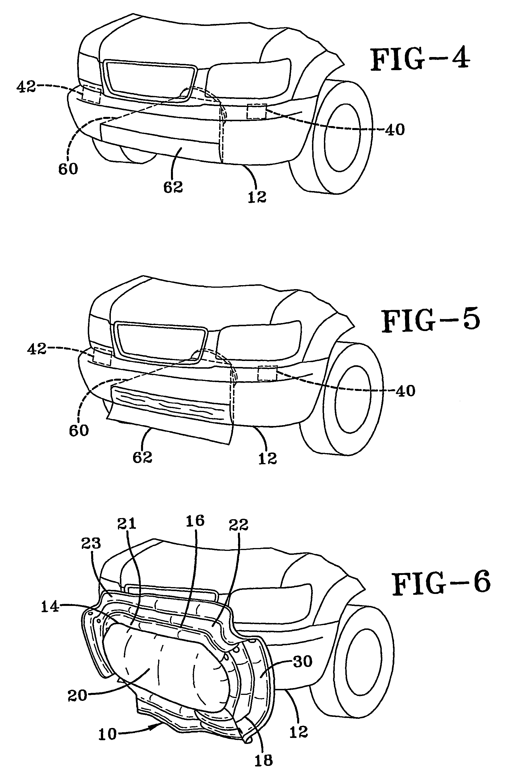
[0015]The present invention is a multi-chambered airbag for use in conjunction with the bumper of a motor vehicle. The airbag is comprised of a main chamber surrounded by one or more concentric secondary chambers. The secondary chambers are separated from adjacent chambers by frangible seams. Just prior to impact the main chamber is inflated to a first internal pressure, (i.e. the hard condition), so as to reduce the amount of momentum transferred to the struck vehicle. Upon contact, the internal pressure increases and the frangible seams sequentially burst allowing the secondary chambers to inflate. With the inflation of the secondary chambers, the pressure in the airbag decreases creating a soft condition making the secondary chambers soft enough to cushion any contact with the occupant of the struck vehicle. Because the airbag has a larger frontal area then a conventional bumper, it also reduces the momentum transfer by spreading it out over a larger area on the struck vehicle.

Problems solved by technology

The increased popularity of sports utility vehicles (SUVs), passenger trucks and other retail motor vehicles that stand higher than a standard motor vehicle, such as a sedan or sports car, has created new problems in the area of vehicle collisions.

Method used


Image

  • Bumper airbag with multiple chambers
  • Bumper airbag with multiple chambers
  • Bumper airbag with multiple chambers

Examples


Embodiment Construction

[0029]Referring to FIGS. 1–3, a bumper airbag as contemplated by the present invention is generally denoted by reference numeral 10. In these FIGS., the bumper airbag 10 is shown in a partially inflated, deployed state. Though the bumper airbag 10 will be described herein as being mounted to a front bumper of a vehicle, as someone skilled in the art would appreciate, the bumper airbag 10 can also be mounted at other locations around a vehicle such as the vehicle's rear bumper.

[0030]With continued reference to FIGS. 1–3 and reference to FIGS. 7–9, the bumper airbag 10 is formed from stitching together two pieces of fabric to define a rear fabric member 24 and a front fabric member 26. The stitching is sewn along the respective perimeter edges of the two pieces to form, when looking toward the front of the vehicle, atop edge 110, a bottom edge 112, a right edge 114 and a left edge 116. One or more, with two preferred, perimeter stitches 30 are used to couple the fabric members 24, 26....


PUM


Abstract

A multi-chambered bumper airbag for deployment from the bumper of a vehicle in the event of a collision with another vehicle is provided. The airbag comprises a main inflatable portion that, when inflated, absorbs the energy from contact with a structural member of the struck vehicle. The airbag also has one or more secondary inflatable portions concentric with the main inflatable portion. Because the secondary inflatable portions have a lower gas pressure than the main inflatable portion, they are used to cushion the occupant of the struck vehicle should the occupants' head and neck be forced out of the window of the struck vehicle.

Description

CROSS REFERENCE TO RELATED APPLICATION[0001]This application claims priority to Provisional Patent Application having Ser. No. 60 / 261,056, filed Jan. 11, 2001, which is incorporated herein by reference.TECHNICAL FIELD[0002]This invention relates generally to motor vehicle safety devices and in particular to a multi-chambered inflatable airbag for use in the bumper area of a motor vehicle.BACKGROUND OF THE INVENTION[0003]For years, the automotive industry has tried various methods and products to reduce the damage to passengers and vehicles in collisions. Of prime importance are the various systems of vehicle airbags that are deployed upon the sensing of an actual collision. These airbags are located in and about the passenger compartment of the motor vehicle and are inflated to surround and protect the occupants from serious injury.[0004]Other methods of reducing, to some extent, the forces created in a collision from injuring the occupants are various attempts to provide “crush zon...

Claims


Application Information

Patent Timeline
IPC IPC(8): B60R21/34B60R19/20B60R19/48B60R21/16B60R21/231B60R21/232B60R21/233B60R21/2338B60R21/2342B60R21/239B60R21/264B60R21/276B60R21/36B61F19/04
CPCB60R19/205B60R19/48B60R21/2338B61F19/04B60R21/36B60R21/231B60R21/2342B60R21/276B60R2021/23107B60R2021/23316B60R2021/23386B60R21/239
Inventor HAMMER, DAVID R.HANSEN, LARRY K.KALISZ, DEBORAH L.CURRY, PAUL G.PACK, WESLEYBARBAT, SAEED DAVIDPRASAD, PRIYARANJAN
Owner FORD GLOBAL TECH LLC
Learn More