
Fiber optic drop cables suitable for outdoor fiber to the subscriber applications

a technology of fiber optic drop cables and outdoor fiber, applied in the direction of optics, fibre mechanical structures, instruments, etc., can solve the problems of limited bandwidth, copper cables have drawbacks, and transmit a relatively limited amount of data,

Active Publication Date: 2006-04-25
CORNING OPTICAL COMM LLC
View PDF27 Cites 54 Cited by
  • Summary
  • Abstract
  • Description
  • Claims
  • Application Information

AI Technical Summary

Benefits of technology

[0005]One such figure-eight drop cable is disclosed in U.S. Pat. No. 6,546,175 and preferably has a carrier section that does not include strength members. The carrier section of this cable is flexible when split from the messenger section for slack storage; however, the carrier section does not have anti-buckling members so the polymer materials of the carrier section may shrink with environmental temperature changes, thereby causing elevated levels of optical attenuation. Another figure-eight drop cable is disclosed in U.S. Pat. No. 6,356,690 having a carrier section with strength members that provide anti-bucking to the carrier section. Strength members may be a material such as steel that aids in inhibiting the shrinkage of the carrier section; however, the steel strength members make the carrier section relatively stiff, thereby inhibiting slack storage. In other words, the strength members increase the bending radius of the carrier section and when coiled the strength members act like a coiled spring that wants to unwind. Moreover, the potential for elevated attenuation still exists.

Problems solved by technology

However, copper cables have drawbacks because they are large, heavy, and can only transmit a relatively limited amount of data.
In other words, subscribers have a limited amount of available bandwidth due to the constraints of copper cables in the communication network.
But there are certain obstacles that make it challenging and / or expensive to route optical waveguides / optical cables deeper into the communication network, i.e., closer to the subscriber.
The carrier section of this cable is flexible when split from the messenger section for slack storage; however, the carrier section does not have anti-buckling members so the polymer materials of the carrier section may shrink with environmental temperature changes, thereby causing elevated levels of optical attenuation.
Strength members may be a material such as steel that aids in inhibiting the shrinkage of the carrier section; however, the steel strength members make the carrier section relatively stiff, thereby inhibiting slack storage.
Moreover, the potential for elevated attenuation still exists.
Cables have used other strength members such as conventional fiberglass yarns, but they provide less anti-buckling strength than rigid strength members.
The use of a relatively large number of conventional fiberglass yarns increases the manufacturing complexity, increases the cost of the cable, and makes the cable relatively stiff.
Thus, this cable does not meet all of the requirements for a drop cable that is suitable for routing optical waveguides to the subscriber.

Method used


Image

  • Fiber optic drop cables suitable for outdoor fiber to the subscriber applications
  • Fiber optic drop cables suitable for outdoor fiber to the subscriber applications
  • Fiber optic drop cables suitable for outdoor fiber to the subscriber applications

Examples


Embodiment Construction

[0016]The present invention will now be described more fully hereinafter with reference to the accompanying drawings showing preferred embodiments of the invention. The invention may, however, be embodied in many different forms and should not be construed as limited to the embodiments set forth herein; rather, these embodiments are provided so that the disclosure will fully convey the scope of the invention to those skilled in the art. The drawings are not necessarily drawn to scale but are configured to clearly illustrate the invention.

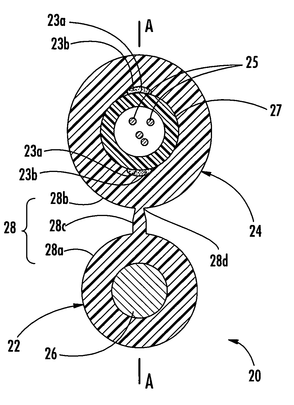
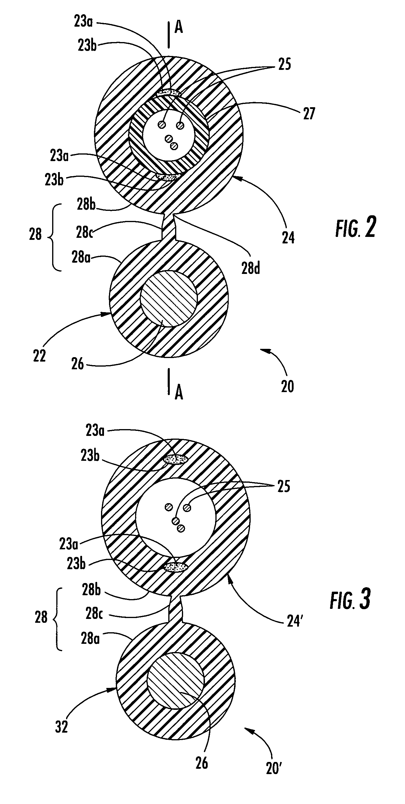
[0017]Illustrated in FIG. 2 is an exemplary figure-eight drop cable 20 (hereinafter cable 20) according to one embodiment of the present invention. Cable 20 includes a messenger section 22 and a carrier section 24 having at least one roving 23 and at least one optical waveguide 25 therein. As depicted, optical waveguides 25 are loose, but they may have other configurations. Messenger section 22 has a messenger jacket 28a and carrier section 24 has a...


PUM


Abstract

A figure-eight fiber optic drop cable includes a messenger section and a carrier section connected by a web. The carrier section has at least one optical waveguide and at least one roving. In one embodiment, the carrier section has an average shrinkage of about 0.5% or less when separated from the messenger section during an average shrinkage test. Also the carrier section of the figure-eight fiber optic drop cable can have an average coefficient of thermal expansion (CTE) section after being separated from the messenger section of about 5.0×10⁻³% / ° C. or less for preserving optical performance. Furthermore, a maximum delta attenuation of the at least one optical waveguide during thermal cycling may be about 0.3 dB / 20 meters or less at a reference wavelength of about 1550 nm at a temperature of about −40° C. Other cable configurations are also possible with the invention.

Description

FIELD OF THE INVENTION[0001]The present invention relates generally to fiber optic drop cables. More specifically, the invention relates to low-cost fiber optic drop cables having enhanced performance characteristics for preserving optical performance in outdoor applications such as fiber to the subscriber.BACKGROUND OF THE INVENTION[0002]Communication networks are used to transport a variety of signals such as voice, video, data transmission, and the like. Traditional communication networks use copper wires in cables for transporting information and data. However, copper cables have drawbacks because they are large, heavy, and can only transmit a relatively limited amount of data. Consequently, optical waveguide cables replaced most of the copper cables in long-haul communication network links, thereby providing greater bandwidth capacity for long-haul links. However, most communication networks use copper cables for distribution and / or drop links on the subscriber side of the cent...

Claims


Application Information

Patent Timeline
Patent Type & Authority Patents(United States)
IPC IPC(8): G02B6/44G02B6/00
CPCG02B6/4433G02B6/4494G02B6/44384
Inventor MOHLER, JAMES D.SEDDON, DAVID A.
Owner CORNING OPTICAL COMM LLC
Learn More