
Fiber optic gyroscope sensing loop doubler

a fiber optic gyroscope and sensing loop technology, applied in the direction of speed measurement using gyroscopic effects, instruments, surveying and navigation, etc., can solve the problems of increasing the bulky package of the gyroscope device, reduce the angle random walk (arw) and bias instability, and improve the performance of the ifog device.

Inactive Publication Date: 2006-04-25
HONEYWELL INT INC
View PDF8 Cites 22 Cited by
  • Summary
  • Abstract
  • Description
  • Claims
  • Application Information

AI Technical Summary

Benefits of technology

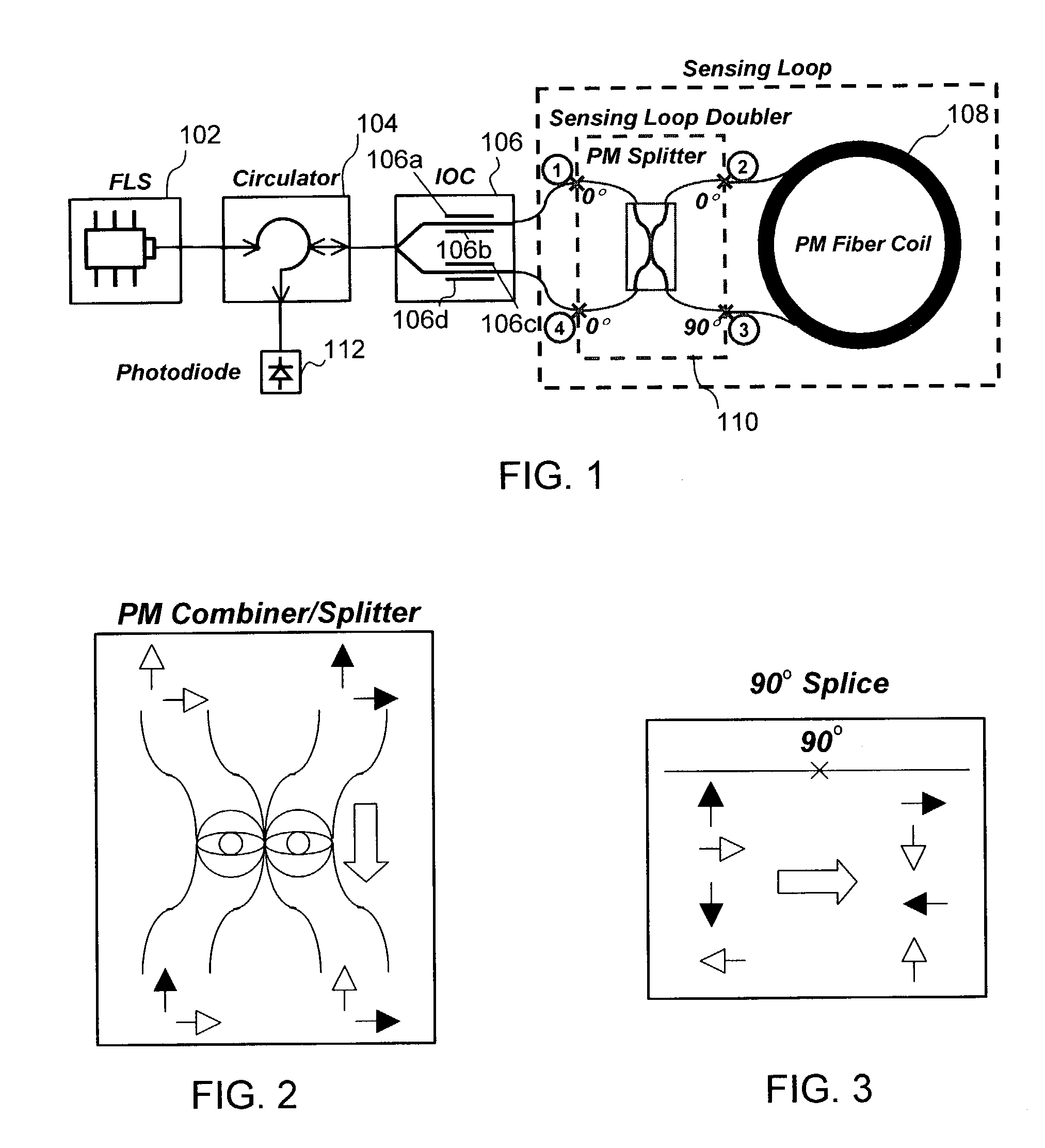
[0005]It is therefore an object of the present invention to improve the performance of an IFOG device without increasing its LD product by physically increasing dimensions, or, alternatively, to maintain the performance of a given IFOG device, but doing so with approximately only half the fiber coil length. The present invention is based on a new technique that routes light inside the fiber coil twice in two orthogonal polarization states, respectively. The polarization-state of the traveling light is preferably controlled by a polarization-maintaining (PM) combiner / splitter. This technique either doubles the sensitivity, and reduces the angle random walk (ARW) and bias instability with the same fiber coil length, or maintains the gyro performance of a given IFOG using only half of fiber coil length.

Problems solved by technology

However, large coil volume resulting from greater fiber length or larger loop diameter (to achieve a higher LD product) requires increasingly bulky packages for the gyroscope device, especially when compared to other technologies such as the ring laser gyroscope (RLG) or hemisphere resonant gyroscope (HRG).

Method used


Image

  • Fiber optic gyroscope sensing loop doubler
  • Fiber optic gyroscope sensing loop doubler
  • Fiber optic gyroscope sensing loop doubler

Examples


second embodiment

V. Second Embodiment

[0063]FIGS. 8 and 9 illustrate a second embodiment of the present invention in which a pair of PM Combiner / Splitters are employed to achieve a sensing loop doubler. Here, a symmetric PM Coupler / Splitter configuration is achieved and light travels through and cross legs twice for each of the PM Coupler / Splitters. This provides a more balanced configuration.

[0064]Possible splices configuration for the symmetric configuration according to the second embodiment include the following:

[0065]Since 0 deg polarization light will go cross leg, and 90 deg polarization will go through the same leg (which is preferred because of fewer 90 degree splices), the following are possible splice arrangements:[0066]Splice 1, 0 deg;[0067]Splice 2, 0 deg;[0068]Splice 3, 90 deg;[0069]Splice 4, 0 deg;[0070]Splice 5, 0 deg[0071]or[0072]Splice 1, 0 deg;[0073]Splice 2, 90 deg;[0074]Splice 3, 0 deg;[0075]Splice 4, 0 deg;[0076]Splice 5, 0 deg

[0077]If the PM Combiner / Splitter legs 1 and 2 are s...

third embodiment

VI. Third Embodiment

[0079]FIGS. 10–12 illustrate a third embodiment of the present invention. Here, instead of employing one or more PM Combiner / Splitters, sensing loop travel doubling can be achieved using a polarization beam splitter that can be implemented using, for example, bulk optics. Alternatively, polarization beam splitter could be implemented using micro optics technique, which could integrate other components such as the circulator, coupler or IOC, among others.

[0080]Referring to FIGS. 10A and 10B, the function of the polarization beam splitter is similar to the PM Combiner / Splitter. It allows one polarization state to pass through the splitter, and the other perpendicular polarization state to be reflected back at the interface via total internal reflection.

[0081]The polarization beam splitter can be made using two optical materials with different indexes of refraction. The refraction index is chosen such that one polarization of the 45° incident light on the interface ...


PUM


Abstract

A fiber optic ring interferometer, such as an interferometric fiber optic gyro (IFOG), with a sensing loop doubler. The IFOG device includes a light source, a circulator in optical communication with the light source and a photo diode, an integrated optical chip (IOC) capable of splitting light emitted from the circulator into two paths each of which is capable of being modulated, the IOC further being capable of combining light from each of the two paths when light travels in a direction towards the circulator, a fiber coil, and a polarization maintaining (PM) combiner / splitter disposed in between the IOC and the fiber coil. The PM combiner / splitter operates to send light through the fiber coil a first time in a first polarization state and to subsequently send the same light a second time through the fiber coil in a second orthogonal polarization state, whereby light travels twice the distance compared to a single loop IFOG device and, as such, effectively doubles the LD product.

Description

BACKGROUND[0001]1. Field of the Invention[0002]The present invention relates to interferometric fiber optic gyroscopes (IFOGs). More particularly, the present invention relates to an IFOG having double the sensitivity, reduced angle random walk (ARW), and increased bias stability compared to an IFOG having the same fiber coil length and loop diameter. The present invention also relates to an IFOG that has the same gyro performance of a conventional IFOG, but that uses only half the fiber coil length of the conventional device.[0003]2. Background of the Invention[0004]As is well-known, in an interferrometric fiber optic gyroscope (IFOG), an optical fiber is wound in a circular or looped shape and acts as a sensing device to detect a Sagnac phase difference for two counter-propagating waves in presence of rotation. The product of the length and diameter (LD product) of the wound fiber sensing-coil determines, to a large degree, the sensitivity of the gyroscope. Generally speaking, the...

Claims


Application Information

Patent Timeline
Patent Type & Authority Patents(United States)
IPC IPC(8): G01C19/72
CPCG01C19/722G01C19/72
Inventor CHEN, CHUNG-JENSTRANDJORD, LEE K.
Owner HONEYWELL INT INC
Learn More