
Camera apparatus and method of taking pictures including simplified processing

a technology of camera and processing method, applied in the field of camera equipment, can solve the problems of limited size of memory medium provided in the digital camera, difficulty for users not familiar with the camera, and unrealistic scheme, and achieve the effect of simplifying the noise removal processing

Inactive Publication Date: 2006-04-25
RICOH KK
View PDF16 Cites 16 Cited by
  • Summary
  • Abstract
  • Description
  • Claims
  • Application Information

AI Technical Summary

Benefits of technology

This approach allows for improved image quality in critical areas while reducing processing time, enhancing the camera's performance by prioritizing processing in areas of high importance and streamlining operations in less critical regions, thus minimizing shutter lag and improving user experience.

Problems solved by technology

In the art of analog cameras, various schemes have been presented to attend to automatic control of camera functions such as focus adjustment and exposure correction, which are often difficult to users who are not familiar with cameras.
Since the size of memory medium provided in the digital camera is limited, the image processing apparatus disclosed in this document divides an image prior to compression, rather than compresses / decompresses the entirety of processed data at once.
This scheme is thus not realistic.
If the highest image quality is to be maintained for the entire image, however, processing time becomes lengthy.
As described above, conventional digital still cameras have drawbacks in that the user is likely to miss a shutter chance because of a lengthy processing time if sophisticated processing steps are used in the image processing to improve image quality.
In analog cameras, however, such function to detect a direction of user sight has only been used for controlling of focus and exposure, and is devoid of any concept that suggests use of such function for improving image quality.

Method used


Image

  • Camera apparatus and method of taking pictures including simplified processing
  • Camera apparatus and method of taking pictures including simplified processing
  • Camera apparatus and method of taking pictures including simplified processing

Examples


first embodiment

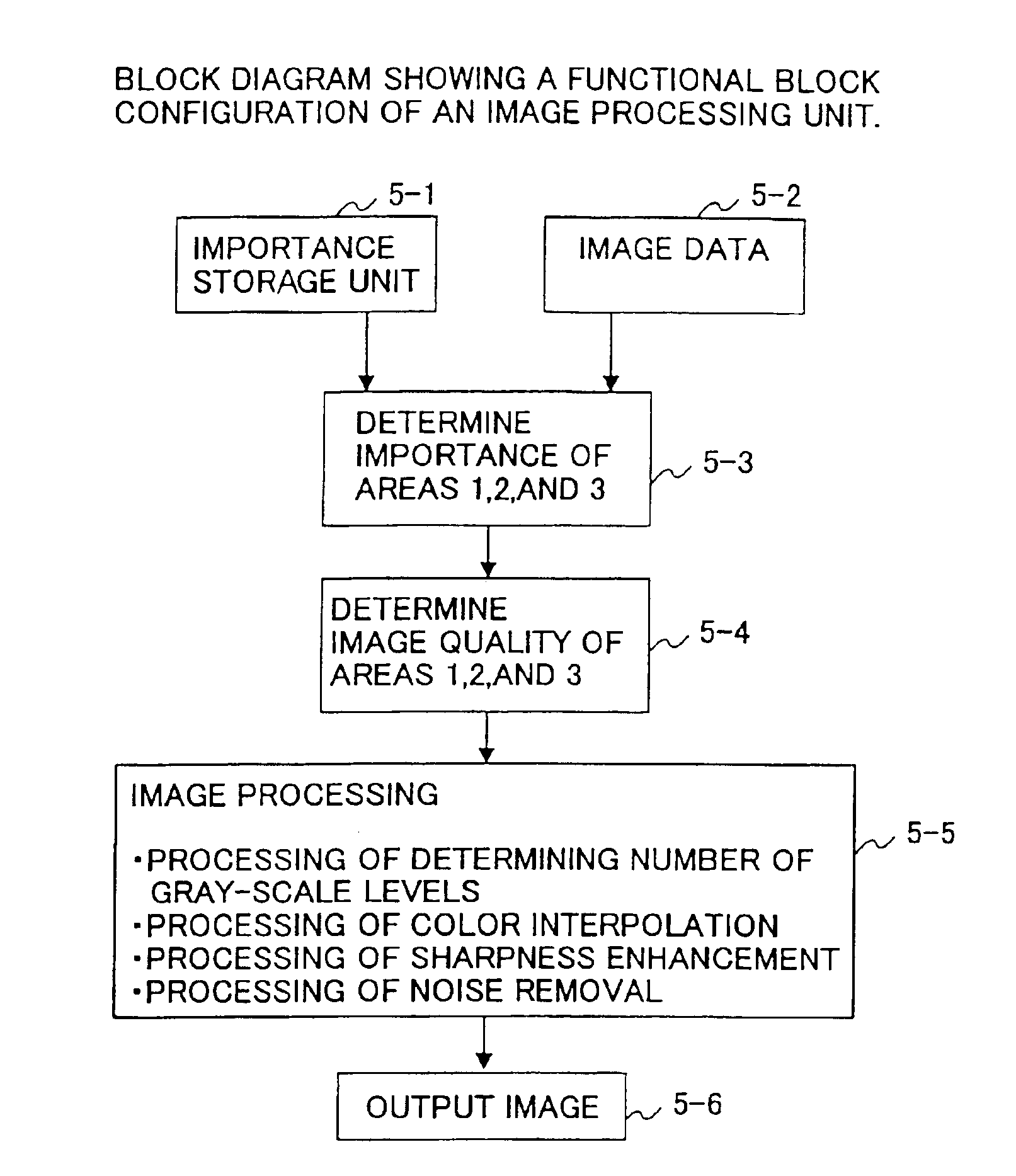
[0120]FIG. 15 is a flowchart of processing that makes image quality vary depending on levels of importance.

[0121]In the first embodiment, a nature of gray-scale representation is given a greater consideration in areas of great importance than in other areas. This makes it possible to improve image quality in the areas of great importance, and, at the same time, can reduce the required memory volume and step up the image processing speed compared with a case in which the same level of gray-scale representation is applied across the board to the entire image.

[0122]At a step ST1, importance of each area is retrieved from the importance storage unit 14. At a step ST2, image data is supplied from the A / D conversion unit 3.

[0123]At a step ST3, importance is determined by identifying an area to which the pixel X of interest belongs. At a step ST4, the means for determining the number of gray scale levels determines the number of gray scale levels. When the areas 1 through 3 have importance...

second embodiment

[0137]FIG. 16 is a flowchart of processing that makes image quality vary depending on levels of importance.

[0138]When a camera device is a CCD with a primary color array, a color filter as shown in FIG. 17 is used. In this case, any given pixel is provided with only one color selected from R, G, and B, so that colors of the two remaining colors need to be interpolated. A process for interpolating color information is referred to as color interpolation processing.

[0139]As can be seen from FIG. 17, the density of G pixels is twice as great as the density of R pixels or the density of B pixels in the primary color array. This is because human visual perception of luminance is relatively greater for the G component. Interpolation of the G color is thus performed more rigidly than interpolation of the two other colors.

[0140]In this embodiment, color interpolation processing is given a greater consideration in areas of great importance than in other areas. This makes it possible to improv...

third embodiment

[0158]FIG. 20 is a flowchart of processing that makes image quality vary depending on levels of importance.

[0159]In the third embodiment, processing for improving image sharpness is changed according to the importance levels of respective image areas. The processing for improving sharpness is also called an aperture correction, which enhances edge portions of the image. In order to enhance edge portions, a check needs to be made first as to whether the pixel of interest is part of an edge portion. Such a check is made by using G signals based on the assumption that G values are good representative of luminance levels.

[0160]In this embodiment, the check for determining whether the pixel of interest is part of an edge portion and the processing for improving sharpness are performed more diligently in areas of great importance than in other areas. This makes it possible to improve image quality in the areas of great importance, and, at the same time, can step up the processing speed co...


PUM


Abstract

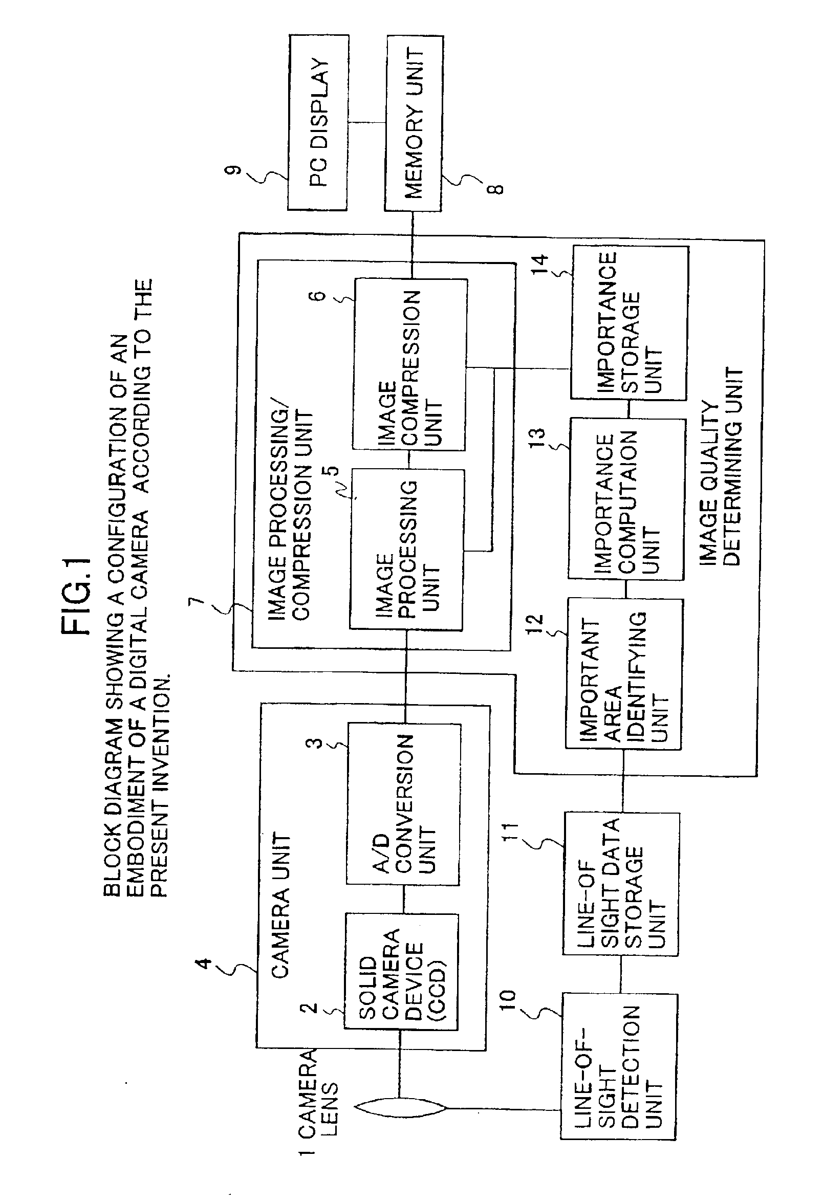
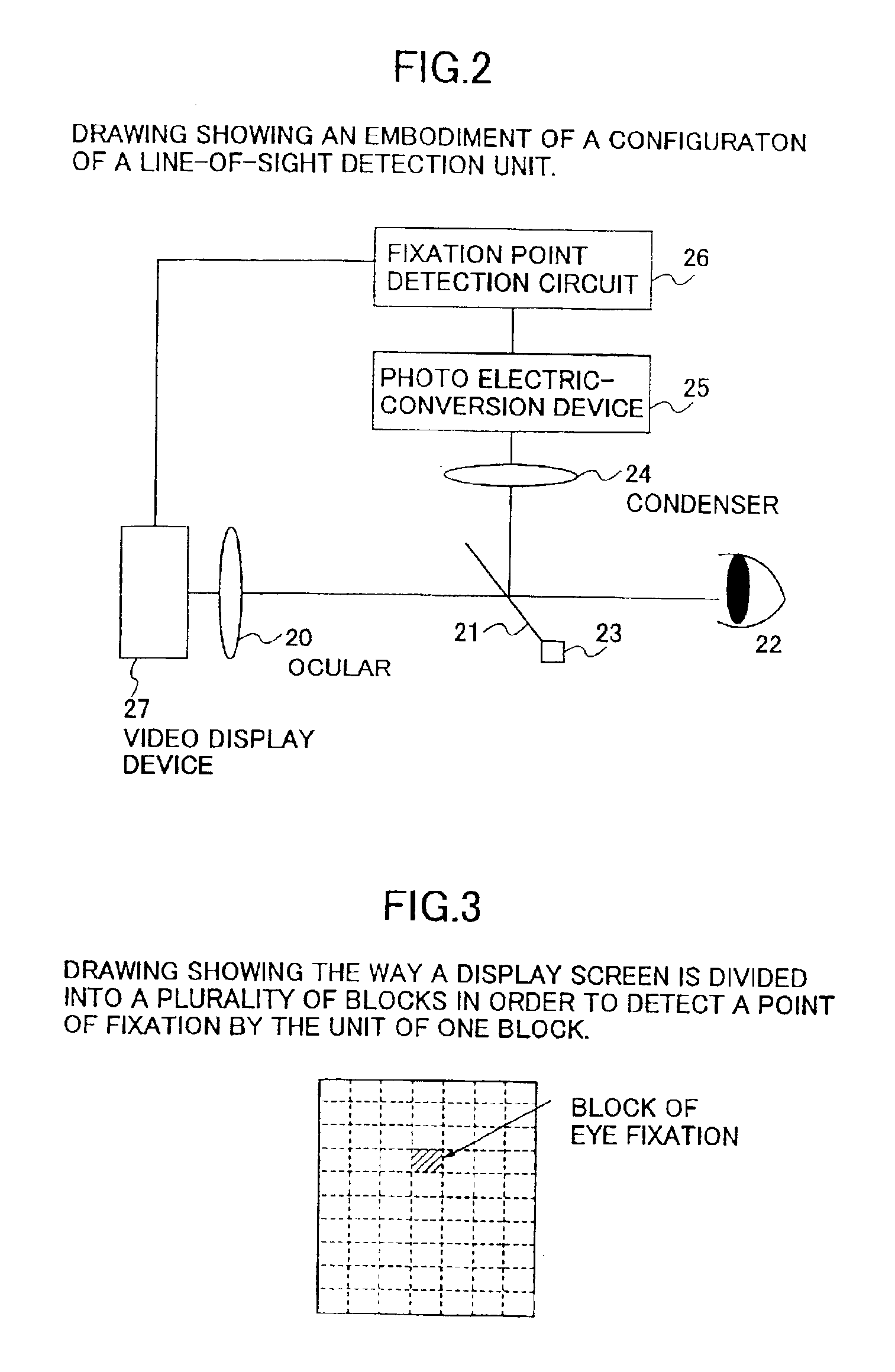
A camera apparatus including a camera unit which acquires an image, a line-of-sight detection unit which detects a point of eye fixation of a user within a camera screen, and an importance computation unit which determines levels of importance for respective areas of the image acquired by the camera unit in accordance with the detection by the line-of-sight detection unit. Also included is a number-of-gray-scale-level determining unit which changes a number of gray scale levels for the respective areas of the image in response to the determination by the importance computation unit.

Description

BACKGROUND OF THE INVENTION[0001]1. Field of the Invention[0002]The present invention generally relates to a camera apparatus, and particularly relates to a digital camera which attends to different image processing, depending on different importance of image areas.[0003]2. Discussion of the Background[0004]Conventionally used cameras are mostly analog cameras that expose films to light. Data photographed by such analog cameras are generally referred to as “photographs”. In the art of analog cameras, various schemes have been presented to attend to automatic control of camera functions such as focus adjustment and exposure correction, which are often difficult to users who are not familiar with cameras. Such automatic control is performed, for example, by providing a function to detect a direction of sight to identify an area of the finder that the user is looking at, and by focusing at the point of fixation.[0005]Japanese Patent Laid-open Application No. 6-138377 discloses an analo...

Claims


Application Information

Patent Timeline
Patent Type & Authority Patents(United States)
IPC IPC(8): H04N5/202H04N3/14H04N5/208H04N5/217G06T5/00G06T5/20H04N1/333H04N1/409H04N1/46H04N5/20H04N5/21H04N23/12H04N101/00
CPCH04N1/3333H04N5/20H04N5/208H04N2201/33342H04N2101/00
Inventor MATSUSHIMA, YUKI
Owner RICOH KK
Learn More