
Image display system scrolling image at high speed using data compression

a display system and image technology, applied in the direction of navigation instruments, distance measurement, instruments, etc., to achieve the effect of high speed, maintaining the resolution of the displayed image, and high speed without decreasing the resolution of the image data

Inactive Publication Date: 2006-04-25
DENSO CORP
View PDF16 Cites 7 Cited by
  • Summary
  • Abstract
  • Description
  • Claims
  • Application Information

AI Technical Summary

Benefits of technology

[0008]To achieve the above object, an image display system is provided with the following. When start of scrolling a displayed image is commanded, a given portion of image data is retrieved. Here, the given portion of the image data includes the image data that are to be displayed at scrolling. The given portion is then compressed to generate compressed data. The compressed data are expanded to generate expanded data. By using the expanded data, the displayed image is scrolled. This structure enables the image data to be displayed at scrolling at high speed without decreasing resolution of the image data. This results in maintaining a recognizable displayed image even at scrolling.
[0009]It is preferable that the image data are compressed by substituting another piece of color information for a certain piece of the color information of a certain pixel included in the image data. This structure enables a data amount of the image data to be effectively decreased. This results in realizing high speed at scrolling.

Problems solved by technology

The above problem is remarkably exhibited in a car navigation system that has an image-scrolling function.
The car navigation system typically has a low memory amount of VRAM due to cost restriction, while the system is required to display high-speed and recognizable scrolling image.

Method used


Image

  • Image display system scrolling image at high speed using data compression
  • Image display system scrolling image at high speed using data compression
  • Image display system scrolling image at high speed using data compression

Examples


first embodiment

[0024](First Embodiment)

[0025]An image display system of a first embodiment of the present invention is mounted in a car navigation system 3 and capable of displaying a map image by scrolling. A display 1 is, for instance, an in-vehicle liquid crystal display, and executes stationary displaying and scroll displaying. An in-vehicle head-up display that displays an image on a windshield of a vehicle can be used for as the display 1.

[0026]A remote control 2 is multi-functional and equipped with scroll-direction keys. A user can start to scroll the map image towards a certain direction by pushing the scroll-direction key. This operation can be inputted also through a touch panel display integrated in the display 1 or a compact keyboard such as a pocket board.

[0027]The car navigation system 3 includes a memory 4, an ECU 5, a display controller 6, a VRAM 7, and an image signal generator 8. The image signal generator 8 generates, from map data or expanded data, image signals for executing ...

second embodiment

[0052](Second Embodiment)

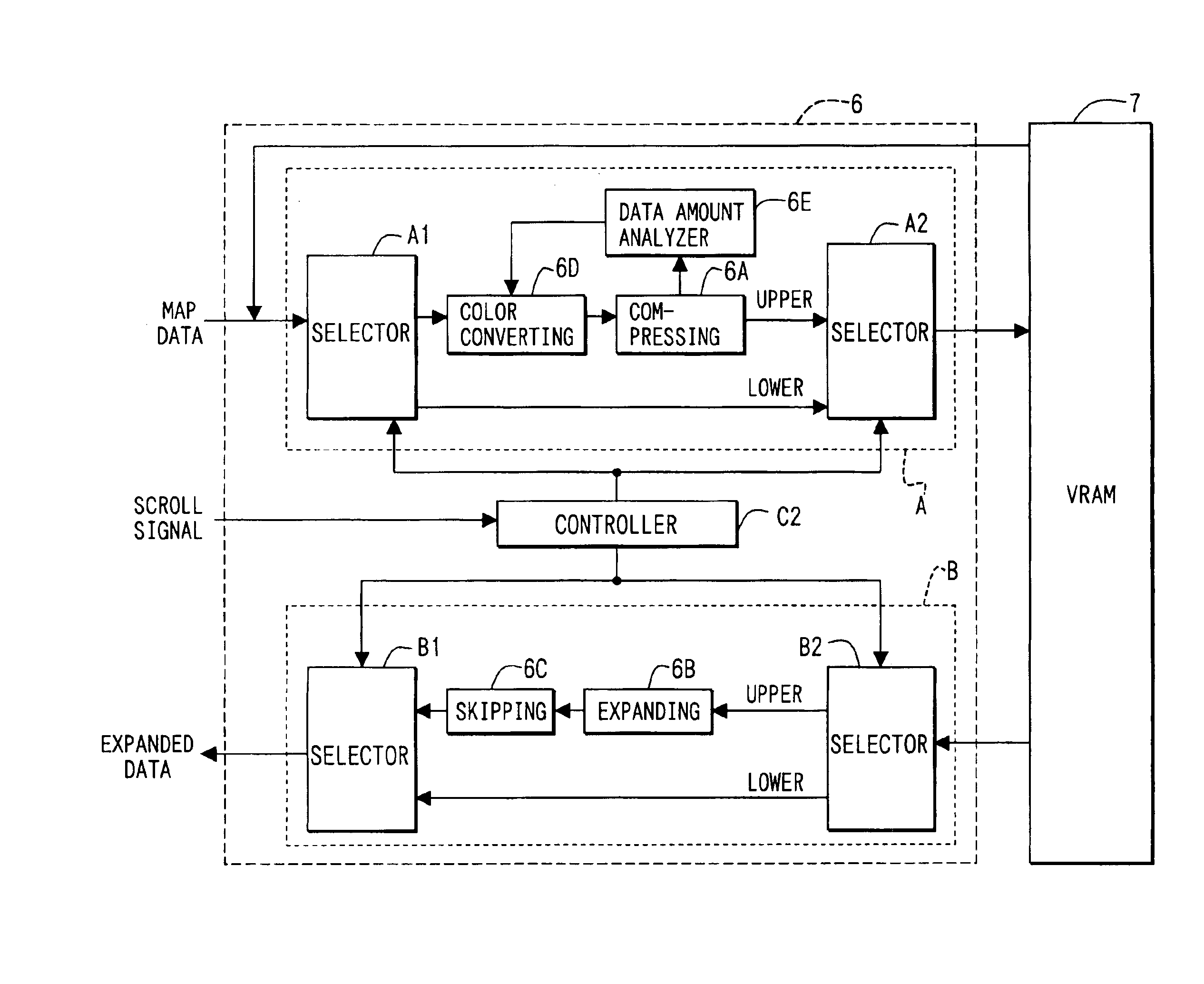
[0053]As shown in FIG. 5, in a second embodiment, a color converting unit 6D is provided in the compressing section A of the display controller 6. This is different from the first embodiment.

[0054]The controller C2 outputs color-related information to the color converting units 6D along with controlling switching of selectors A1, A2, B1, and B2. The color-related information includes a color converting method of division map data, color information necessary for a case where pixel data included in the division map data are substituted, and replacement-prohibited color information that is prohibited from being replaced. These are obtained from the ECU 5 and can be set through the remote control 2 by the user.

[0055]The color converting unit 6D is formed of a plurality of parts that replaces color information of the pixels included in the division map data, as shown in FIG. 6.

[0056]A mode register 65 stores the above color-related information and controls color...

third embodiment

[0078](Third Embodiment)

[0079]As shown in FIG. 11, in a third embodiment, a data amount analyzer 6E is provided in the compressing section A of the display controller 6. This is different from the second embodiment.

[0080]The data amount analyzer 6E compares, with a predetermined data amount, a data amount of certain compressed data generated by the compressing unit 6A. Here, the certain compressed data are generated by compressing certain division map data. When the data amount of the certain compressed data is more than the predetermined data amount, the data amount analyzer 6E commands the color converting unit 6D to output another color-converted division map data to the compressing unit 6A. Here, the another color-converted division map data include color information whose data amount is not more than that of the color information of the above certain division map data. Other structure of the third embodiment is similar to that of the first or second embodiment, so that explanat...


PUM


Abstract

When a user pushes a scroll-direction key, an ECU obtains, from a memory, a division map corresponding to a division located in a direction designated by the scroll-direction key. The ECU then outputs the division map to a display controller. The display controller compresses the division map to store in a VRAM. At scrolling a displayed image, the display controller expands the compressed division map. It then outputs, to an image signal generator, only a necessary portion of the expanded division map. Thereby, the displayed image can be scrolled at high speed and easily recognizable for the user.

Description

CROSS REFERENCE TO RELATED APPLICATIONS[0001]This application is based on and incorporates herein by reference Japanese Patent Application No. 2002-205492 filed on Jul. 15, 2002.FIELD OF THE INVENTION[0002]The present invention relates to an image display system scrolling an image at high speed by utilizing data compression.BACKGROUND OF THE INVENTION[0003]A method of scrolling an image (image-scrolling) at high speed is disclosed in JP-A-H11-161158. In this method, resolution of a displayed image at scrolling is decreased to one half to realize high-speed scrolling. Namely, when original map data shown in the upper portion of FIG. 13 are used for image-scrolling, scrolling map data are generated by thinning the original map data vertically and horizontally every other line as shown in the lower portion of FIG. 13. While the resolution of the scrolling map data is a half of the resolution of the original map data, a data amount of the scrolling map data is one fourth of that of the ...

Claims


Application Information

Patent Timeline
Patent Type & Authority Patents(United States)
IPC IPC(8): G06T9/00G09B29/00G01C21/00G01C21/26G01C21/36G06F3/14G08G1/0969G09G5/02G09G5/34G09G5/36
CPCG01C21/367G09G5/346H04N19/426H04N19/186H04N19/17H04N19/44H04N19/132G09G5/024G09G2340/02
Inventor MORISHITA, YOJI
Owner DENSO CORP
Learn More