
Multimeter with filtered measurement mode

a multimeter and measurement mode technology, applied in the field of digital multimeters, can solve the problems of rms voltage measurement values reading erroneously higher than, extreme difficulty in making accurate measurements, etc., and achieve the effect of facilitating the ability to accurately measure the frequency

Active Publication Date: 2006-04-25
JOHN FLUKE MFG CO INC
View PDF15 Cites 70 Cited by
  • Summary
  • Abstract
  • Description
  • Claims
  • Application Information

AI Technical Summary

Benefits of technology

The present invention provides a multimeter with a filtered measurement mode. This mode allows for accurate measurement of the frequency of a variable-speed motor drive using high-frequency pulses. The multimeter includes a low-pass filter and a programmable switching circuit that can select between the output of the RMS converter and the output of the low-pass filter for further processing by measurement circuitry. This filtered measurement mode is useful in measuring the outputs of modem adjustable speed motor drives, uninterruptible power sources, and switching power supplies.

Problems solved by technology

However, there are a number of measurement situations confronting the technician in which it is extremely difficult to make accurate measurements.
The resultant RMS voltage measurement values read erroneously higher than they should because total energy of the combined outputs is being measured.

Method used


Image

  • Multimeter with filtered measurement mode
  • Multimeter with filtered measurement mode
  • Multimeter with filtered measurement mode

Examples


Embodiment Construction

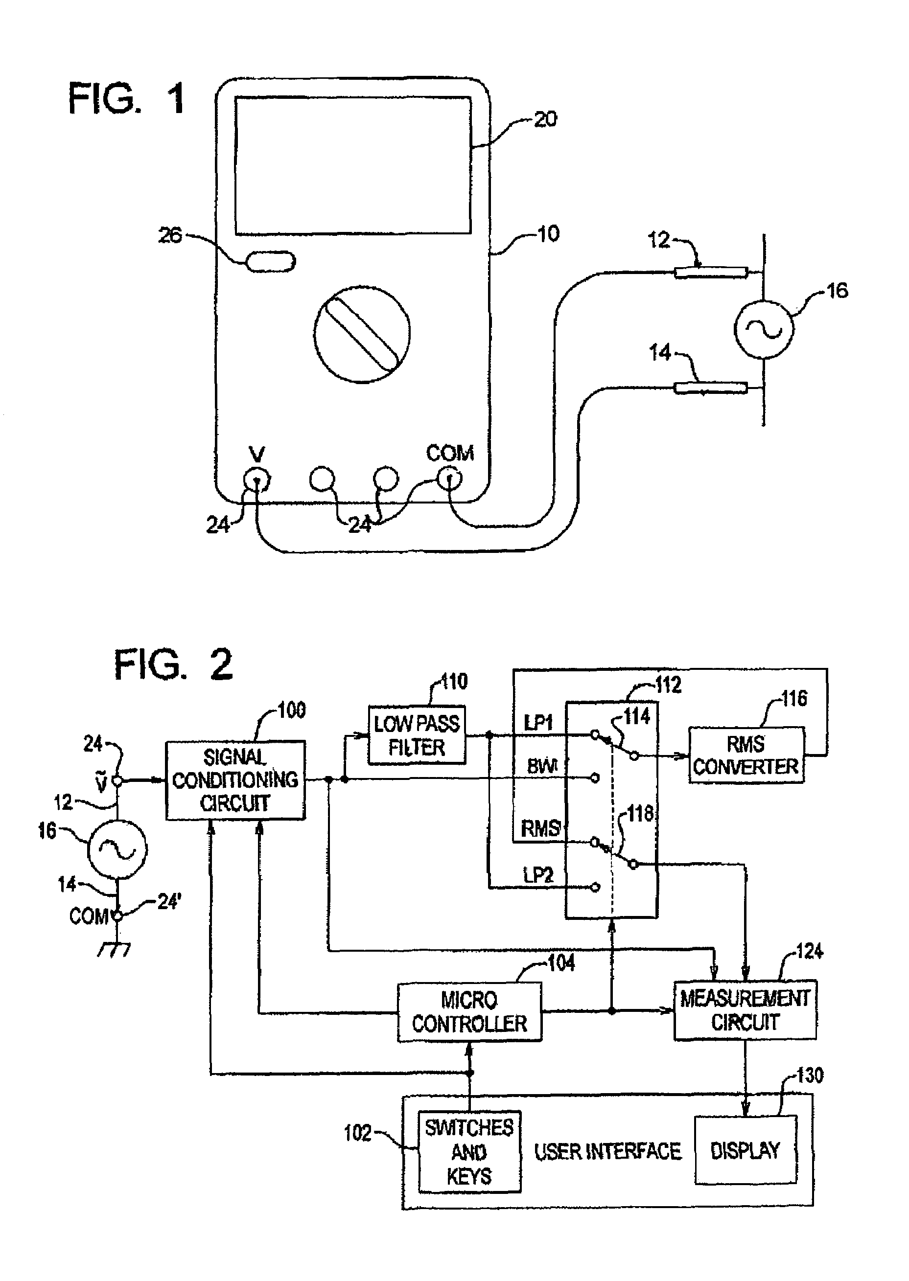
[0014]Referring to FIG. 1 of the drawings, there is shown a schematic plan view drawing of a digital multimeter 10 having a pair of test leads 12 and 14 connected to a circuit under test 16. The details shown in the plan view are referred to as the user interface, and include a display screen 20 for viewing measurement results, a rotary switch 22 for selecting measurement functions and ranges, a plurality of input jacks 24 including at least a volts (V) jack and a common (COM) jack for receiving test leads 12 and 14, and one or more mode-selecting push-button switches or keys 26 for selecting operating modes. For purposes of explaining this invention, key 26 selects between a filtered measurement mode and a normal operating mode.

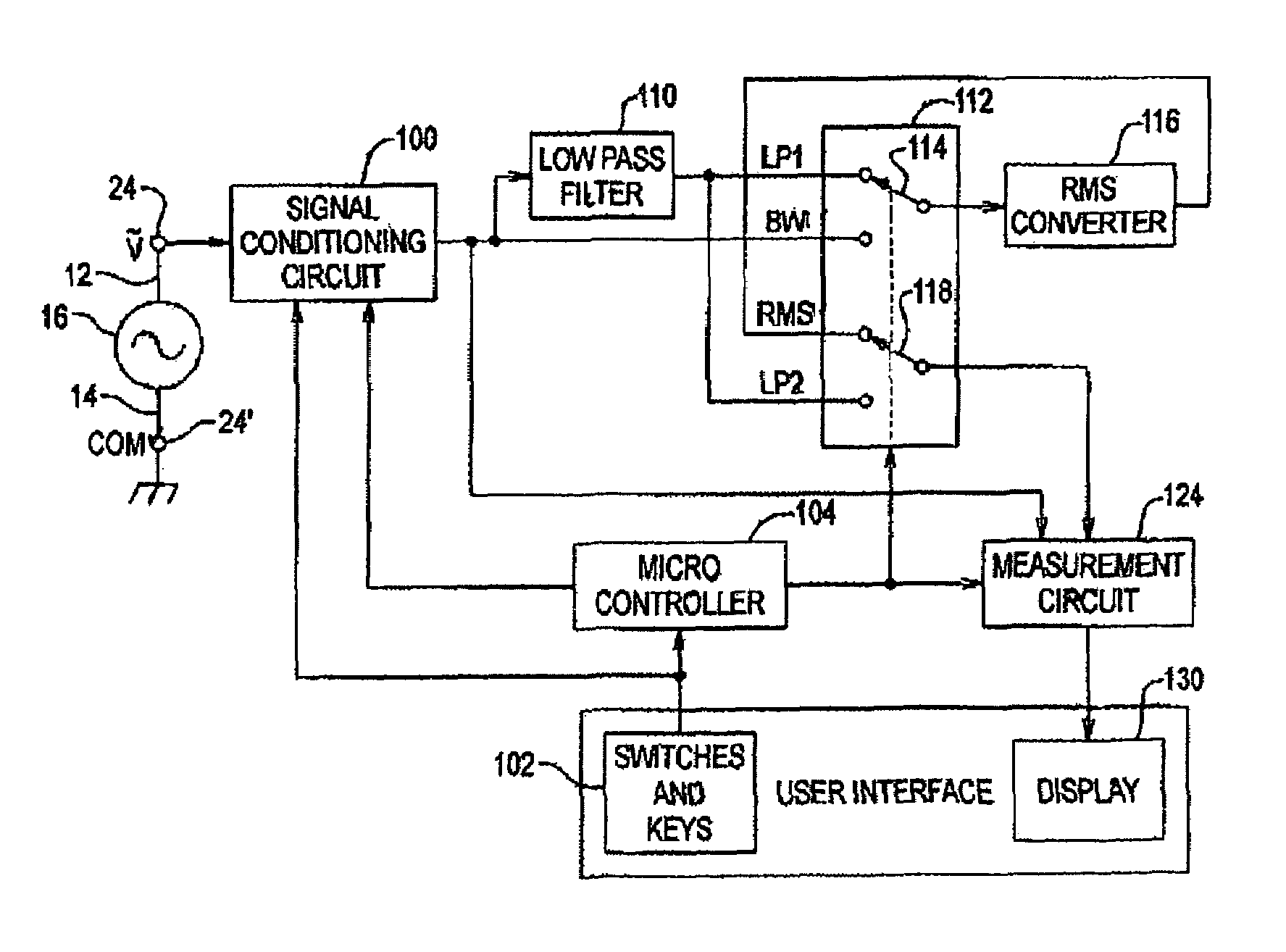
[0015]FIG. 2 is a partial block diagram of the multimeter 10 of FIG. 1. A circuit under test 16 is connected to input jacks 24 (V) and 24′ (COM) via test leads 12 and 14 as described above in connection with FIG. 1. The input signal is applied to a signal co...


PUM


Abstract

A multimeter with a filtered measurement mode. By pressing a single button or key, a low-pass filter is switched into the signal path to filter voltage spikes, noise, and switching transients from pulse-width modulated pulses, or lower frequency sinusoidal signals with higher frequency components, and at the same time an on-screen icon indicates to a user that the filtered mode has been selected. The user can switch back and forth between filtered and unfiltered modes. The filtered measurement mode is useful in measuring the outputs of modern adjustable-speed motor drives, uninterruptible power sources, and switch power supplies.

Description

BACKGROUND OF THE INVENTION[0001]This invention relates generally to digital multimeters, and in particular to a multimeter having a filtered measurement mode.[0002]Digital multimeters measure a wide range of electrical parameters, such as a.c. and d.c. currents and voltages, and resistance as well as physical parameters that can be converted to electrical signals, such as temperature, capacitance, and frequency of events. One commercially available family of digital multimeters favored and used by professional electricians is the Fluke 80 Series. These multimeters have additional measurement capabilities, including true RMS (root-mean-square) voltage measurement, freezing a measurement in a so-called “hold” mode, measuring the minimum and maximum (Min / Max) voltages of a varying signal, and making diode checks. Because these multimeters are capable of accurate RMS voltage measurements over a broad band of frequencies, they are a versatile tool for investigation of power quality prob...

Claims


Application Information

Patent Timeline
Patent Type & Authority Patents(United States)
IPC IPC(8): G01R1/38G01R11/32
CPCG01R15/005
Inventor NEWCOMBE, CHARLES B.
Owner JOHN FLUKE MFG CO INC
Learn More