
Pointing position correcting method, pointing position correcting apparatus, and pointing apparatus

a technology of pointing apparatus and pointing position, which is applied in the direction of identification means, dynamo-electric converter control, instruments, etc., can solve the problems of damage to the appearance of the pointing apparatus and the pointing apparatus cannot point out the correct speed, so as to achieve quick performance and quickly advance the pointer

Active Publication Date: 2006-04-25
YAZAKI CORP
View PDF8 Cites 13 Cited by
  • Summary
  • Abstract
  • Description
  • Claims
  • Application Information

AI Technical Summary

Benefits of technology

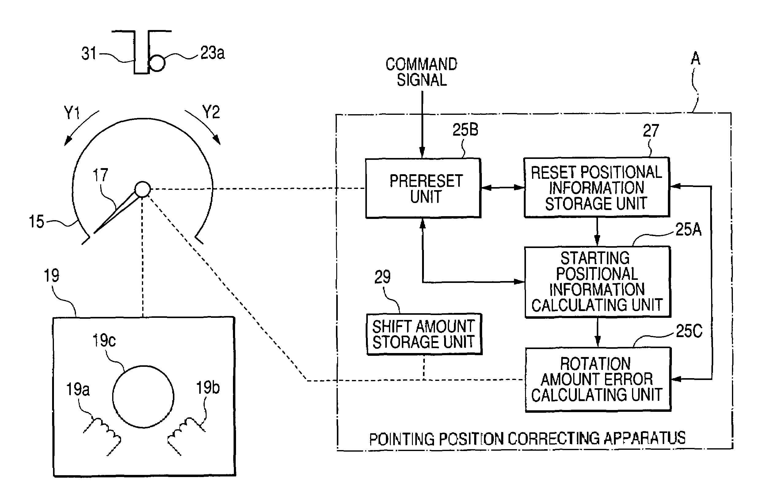
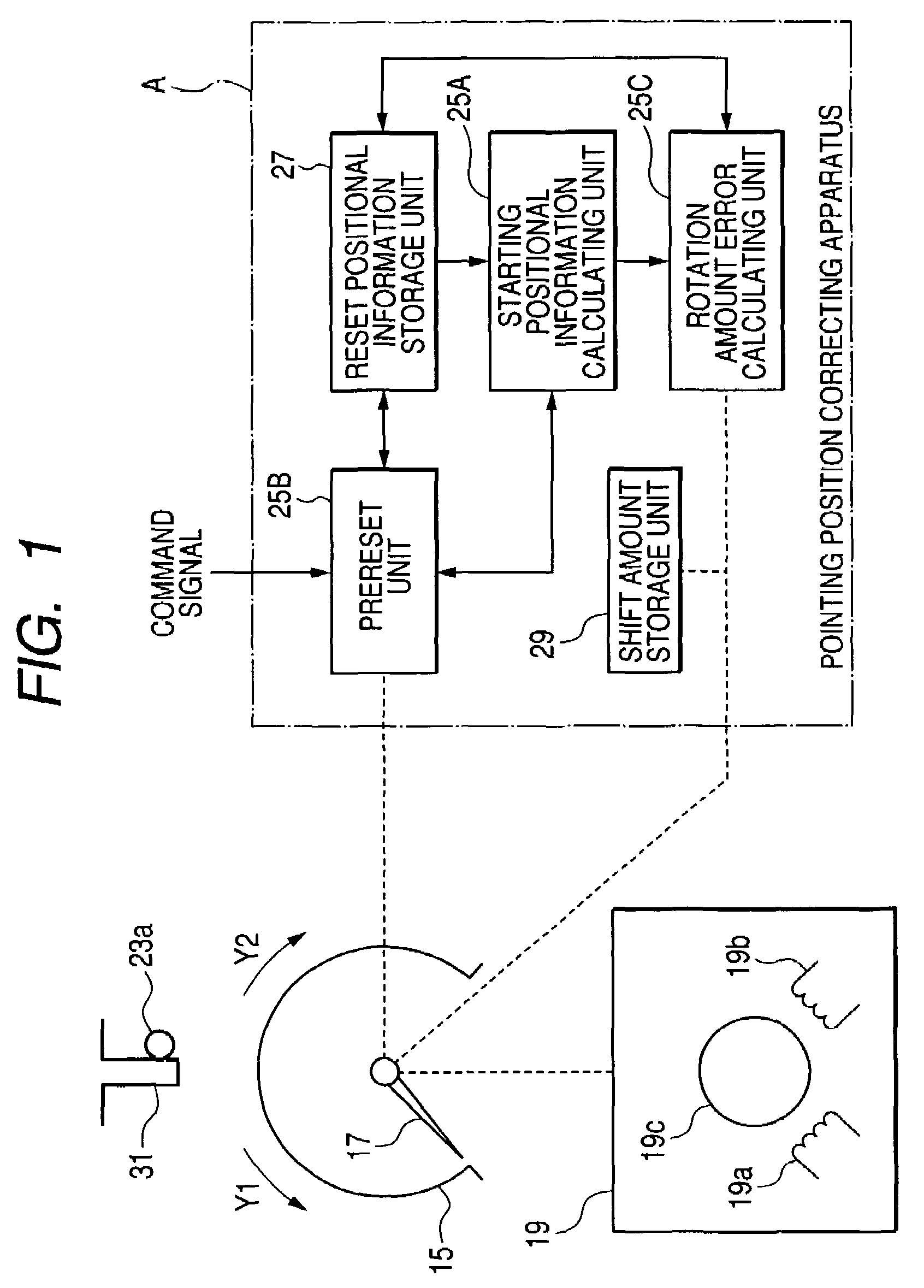
The present invention provides a pointing position correcting apparatus and a pointing apparatus that can quickly perform both a reset operation and a correcting operation to maintain pointing precision as to pointers of meters in a combination meter. This is achieved by performing a proreset operation in which the pointer is rotated to a reset operation starting position, representing a pointing position that is shifted in a plus direction of a scale from a reset position. After the proreset operation, a reset operation is carried out in which the pointer is rotated in a minus direction of the scale to the reset position. A correcting operation is then performed in which the pointer is rotated in the plus direction up to a reference pointing position. The invention allows for faster and more efficient performance of these operations, even in the event of a stopper construction.

Problems solved by technology

As a result, the pointing apparatus cannot point out the correct speed.
However, as explained above, when the stopper 31 is provided on the dial 43 of the pointing device, the appearance of the pointing apparatus may be damaged.

Method used


Image

  • Pointing position correcting method, pointing position correcting apparatus, and pointing apparatus
  • Pointing position correcting method, pointing position correcting apparatus, and pointing apparatus
  • Pointing position correcting method, pointing position correcting apparatus, and pointing apparatus

Examples


Embodiment Construction

[0076]Referring now to drawings, a description is made of an embodiment mode as to a pointing position correcting method and a pointing apparatus to which the above-described correcting method has been applied, according to the present invention.

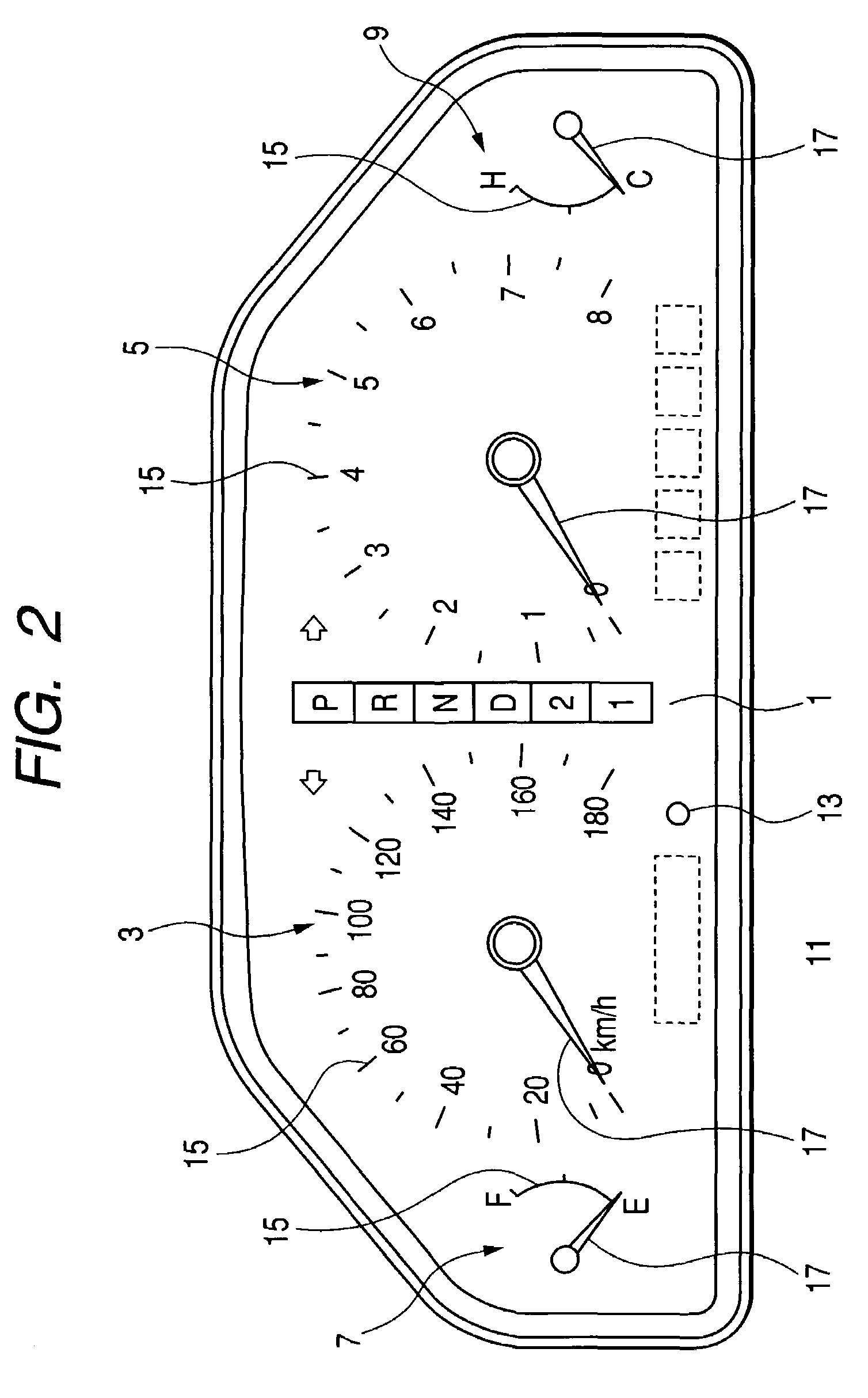
[0077]FIG. 2 is a front view for showing a vehicle-purpose display apparatus into which a pointing apparatus according to an embodiment mode of the present invention has been assembled. The vehicle-purpose display apparatus of this embodiment mode contains a speed indicator 3, an engine tachometer 5, a fuel meter 7, a radiator water temperature meter 9, an odotrip switching type liquid crystal display device 11, and a push button type odotrip switching type switch (will be referred to as “O / T switch” hereinafter) 13, and the like on a character plate indicated by reference numeral 1 shown in FIG. 2.

[0078]Then, the pointing apparatus according to one embodiment mode of the present invention, the schematic structure of which is partially indic...


PUM


Abstract

A method of correcting a pointing position of a pointer rotated by a stepper motor includes the steps of: performing a prereset operation in which the pointer is rotated to a reset operation starting position that represents a pointing position of the pointer which is shifted by a predetermined amount in a plus direction of a scale from a reset position where a pin which is rotated in conjunction with a rotation of the pointer abuts against a fixed stopper; after the prereset operation, performing a reset operation in which the pointer is rotated in a minus direction of the scale to the reset position; and after the reset operation, performing a correcting operation in which the pointer is rotated in the plus direction up to a reference pointing position which is indicated by previously stored reference pointing positional information.

Description

BACKGROUND OF THE INVENTION[0001]The present invention is related to a pointing position correcting method, a pointing position correcting apparatus, and a pointing apparatus, which correct a shift between a pointing position when a rotation of a pointer is stopped by that a driven member rotated in conjunction with a rotation of this pointer abuts against a fixed stopper, and a reference pointing position for pointing a zero on a scale, while the pointer is rotated by a stepper motor in such a manner that this pointer points a place in response to a measurement amount on a scale.[0002]Conventionally, as a pointing apparatus for pointing out a place of a scale responding to a measurement value on a dial by rotating a pointer by a stepper motor, for instance, such a pointing apparatus is known which contains pointers for pointing out a speed of a vehicle and an engine revolution number. As represented in FIG. 12, the above-described pointing apparatus is equipped with a stepper motor...

Claims


Application Information

Patent Timeline
Patent Type & Authority Patents(United States)
IPC IPC(8): H02P8/04H02P8/00H02P8/06B60K35/00G01D11/00H02P8/32H02P8/34
CPCH02P8/34
Inventor OISHI, MASAKI
Owner YAZAKI CORP
Learn More