
Generating light from electromagnetic energy

a technology of electromagnetic energy and light, applied in the direction of discharge tube luminescnet screens, structural circuit elements, sustainable buildings, etc., can solve the problems of focusing the energy into the bulb, the construction of these mechanisms is complex, and the precision of the conventional mechanism for focusing the energy is not high enough, so as to prevent the leakage of non-visible electromagnetic energy and prevent melting or other damage to the plasma lamp

Active Publication Date: 2006-04-25
V SILICON SEMICON (HANGZHOU) CO LTD
View PDF8 Cites 73 Cited by
  • Summary
  • Abstract
  • Description
  • Claims
  • Application Information

AI Technical Summary

Benefits of technology

[0010]By virtue of the foregoing arrangements, the cylindrical resonator resonates in modes that tend to be tolerant of small variations in the actual height of the resonator. As a result, manufacturing costs for the resonator are reduced. In addition, the non-visible electromagnetic energy is concentrated on the plasma lamp, thereby facilitating efficient conversion of non-visible electromagnetic energy into light.
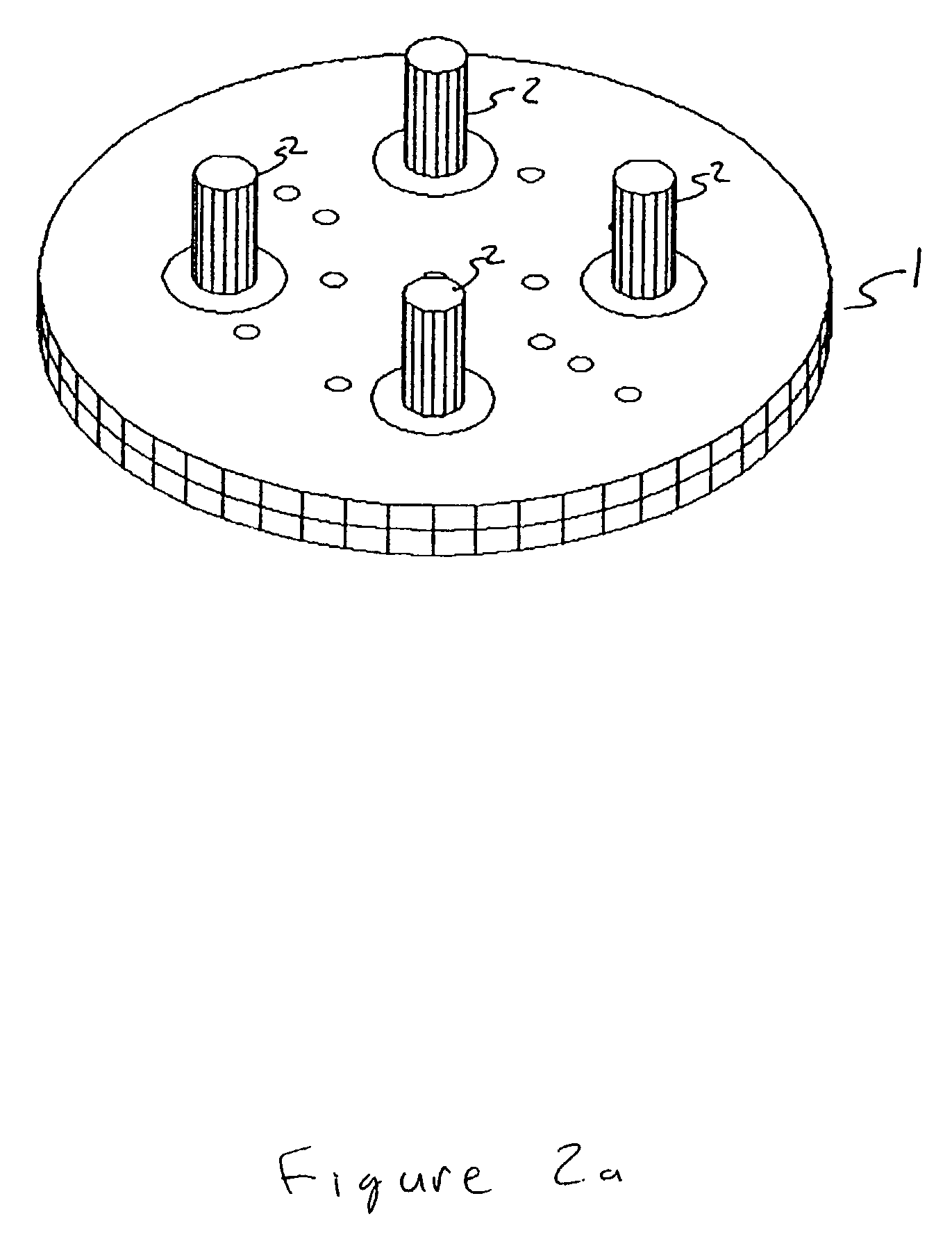
[0012]Preferably, the probes are adjustable within the corresponding through holes so as to allow for tuning of the probes. In one implementation, the lengths of the probes are adjustable from the tops of the through holes. Such adjustable probes could be constructed from a top part and a bottom part threaded together, with the top part including a groove or other indentation for rotary manipulation by a tool (e.g., a screwdriver). Rotation of the top part lengthens or shortens the probe. The resonator itself also can be slightly tunable, for example by insertion of dielectric rods into the through holes on top of the probes so as to tune the resonance of the resonator.
[0013]In order to help prevent leakage of non-visible electromagnetic energy from the top of the central through hole, a quarter wavelength waveguide choke can be placed at the top of the central through hole. Alternatively, a waveguide with a cut off frequency below an operational frequency of the resonator can be placed at the top of the through hole for this purpose.
[0014]The plasma in the plasma lamp can become extremely hot, possibly even hot enough to melt the lamp. An electromagnet or other magnetic field generator can be placed around the resonator so as to bunch plasma in the plasma lamp away from sides of the plasma lamp, thereby helping to prevent melting or other damage to the plasma lamp.

Problems solved by technology

However, problems exist in focusing the energy into a bulb included in the plasma lamp.
First, conventional mechanisms for focusing the energy require extreme precision to work properly.
As a result, construction of these mechanisms is exacting and expensive.
Second, tuning conventional mechanisms to support the most efficient frequencies is problematic.

Method used


Image

  • Generating light from electromagnetic energy
  • Generating light from electromagnetic energy
  • Generating light from electromagnetic energy

Examples


Embodiment Construction

[0034]In this description, the term “non-visible electromagnetic energy” is used for electromagnetic energy outside of the visible spectrum. The invention is envisioned to operate with non-visible electromagnetic energy in the 2 to 5 GHz range, although the invention is not limited to these frequencies. Likewise, the term “light” refers to visible light, as well as to ultraviolet and infrared light.

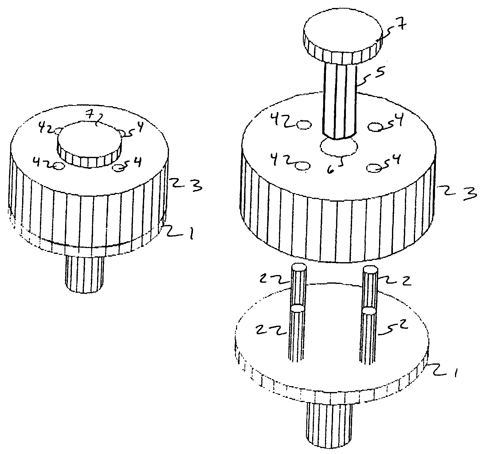
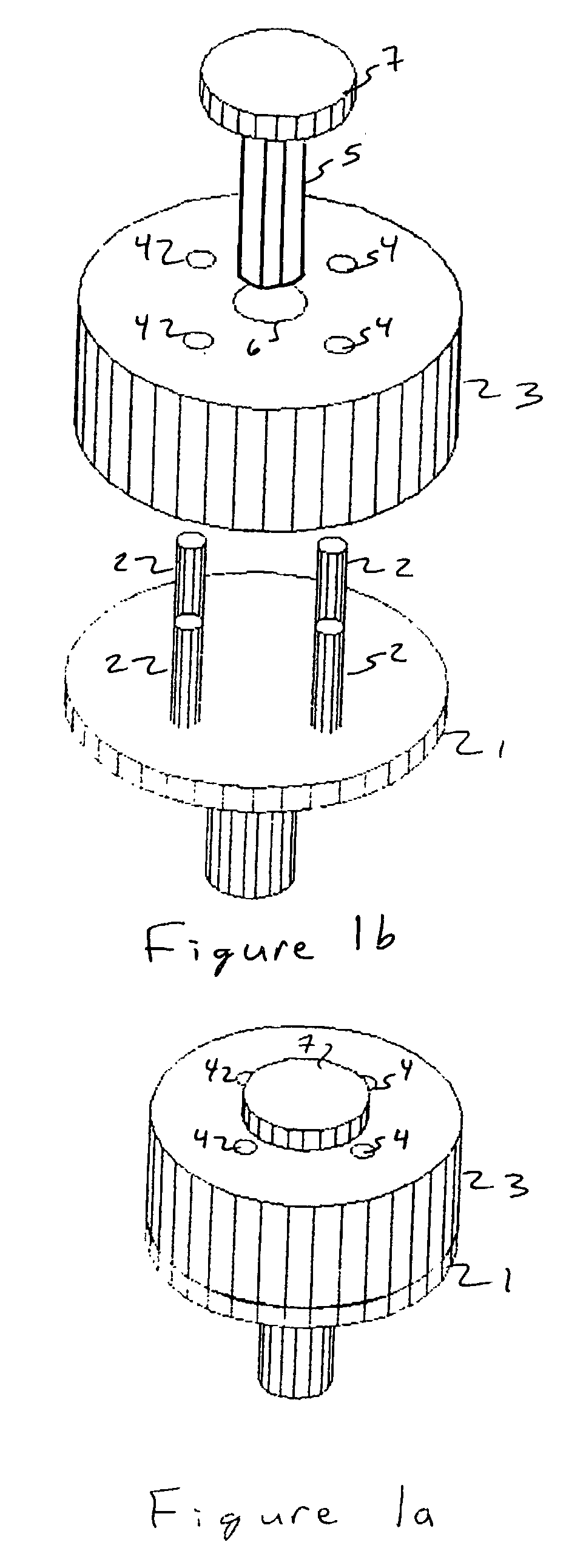
[0035]FIGS. 1a and 1b show a device according to the invention that converts non-visible electromagnetic energy into light. FIG. 11a show the device assembled, and FIG. 1b shows an exploded view of the device.

[0036]Briefly, the implementation shown in FIGS. 1a and 1b includes a cylindrical electromagnetic resonator with a central through hole and with symmetrically displaced through holes surrounding the central through hole. The device also includes a base and probes connected to the base. The probes are placed to introduce non-visible electromagnetic energy into the resonator. The devic...


PUM


Abstract

A device that converts non-visible electromagnetic energy into light. The device includes a cylindrical electromagnetic resonator with a central through hole, a dielectric (preferably ceramic) material surrounded by symmetrically displaced through holes surrounding the central through hole. The device also includes a base and probes connected to the base. The probes are placed to introduce non-visible electromagnetic energy into the resonator. The device also includes a plasma lamp placed in the central through hole. The plasma lamp is placed to convert the non-visible electromagnetic energy into light. Preferably, the resonator is composed of a ceramic with a metalized surface except for inside the through holes. Also, a device that converts electricity into light and vice versa, a device that emits modulated light based on input modulated non-visible electromagnetic energy, and a device that emits modulated non-visible electromagnetic energy based on input modulated light, all implemented using a cylindrical electromagnetic resonator.

Description

CROSS REFERENCE TO PROVISIONAL APPLICATION[0001]This application claims priority from provisional application No. 60 / 337,057 filed Nov. 6, 2001. This provisional application is incorporated by reference as if fully set forth herein.BACKGROUND OF THE INVENTION[0002]1. Field of the Invention[0003]This invention relates to generation of light from electromagnetic energy ranging from the lower megahertz to higher millimeter wave frequencies. In particular, the invention relates to an efficient and fault-tolerant mechanism for coupling the electromagnetic energy into a plasma lamp.[0004]2. Description of the Related Art[0005]One known technique for converting radio-frequency (RF) and other non-visible electromagnetic energy into visible light is to direct the energy into a plasma lamp. The energy heats the plasma, which in turn generates light.[0006]However, problems exist in focusing the energy into a bulb included in the plasma lamp. First, conventional mechanisms for focusing the ener...

Claims


Application Information

Patent Timeline
IPC IPC(8): H01J7/46
CPCH01J7/46H01J65/042Y02B20/22Y02B20/00
Inventor IZADIAN, JAMAL S.DECLUE, LARRYFEALKOFF, DAVID
Owner V SILICON SEMICON (HANGZHOU) CO LTD
Learn More