Eureka AIR delivers breakthrough ideas for toughest innovation challenges, trusted by R&D personnel around the world.

Fluid filled ampoules and methods for their use in aerosolizers

an ampoule and flue gas technology, applied in the field of liquid aerosolization, can solve the problems of tab cracking, seal breaking, etc., and achieve the effects of reducing the chance of droplet spillage, increasing surface area, and convenient access

Inactive Publication Date: 2006-04-25
NOVARTIS FARMA
View PDF494 Cites 88 Cited by
  • Summary
  • Abstract
  • Description
  • Claims
  • Application Information

AI Technical Summary

Benefits of technology

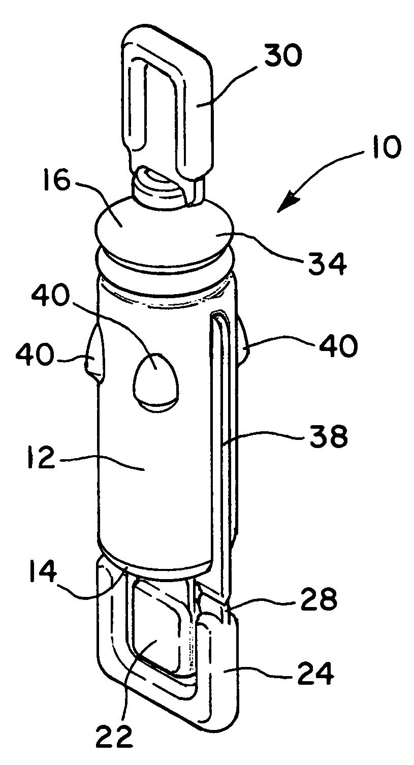
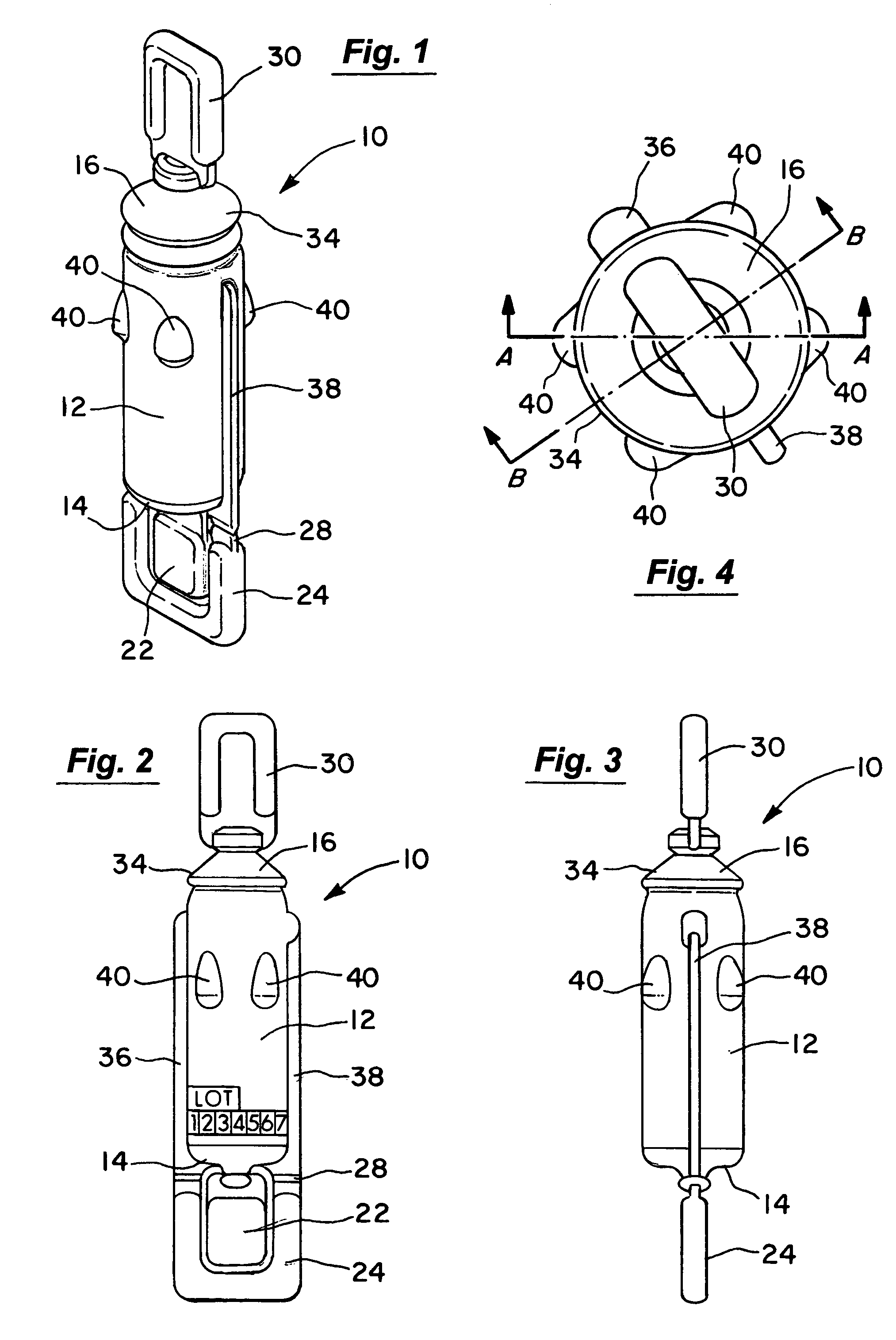
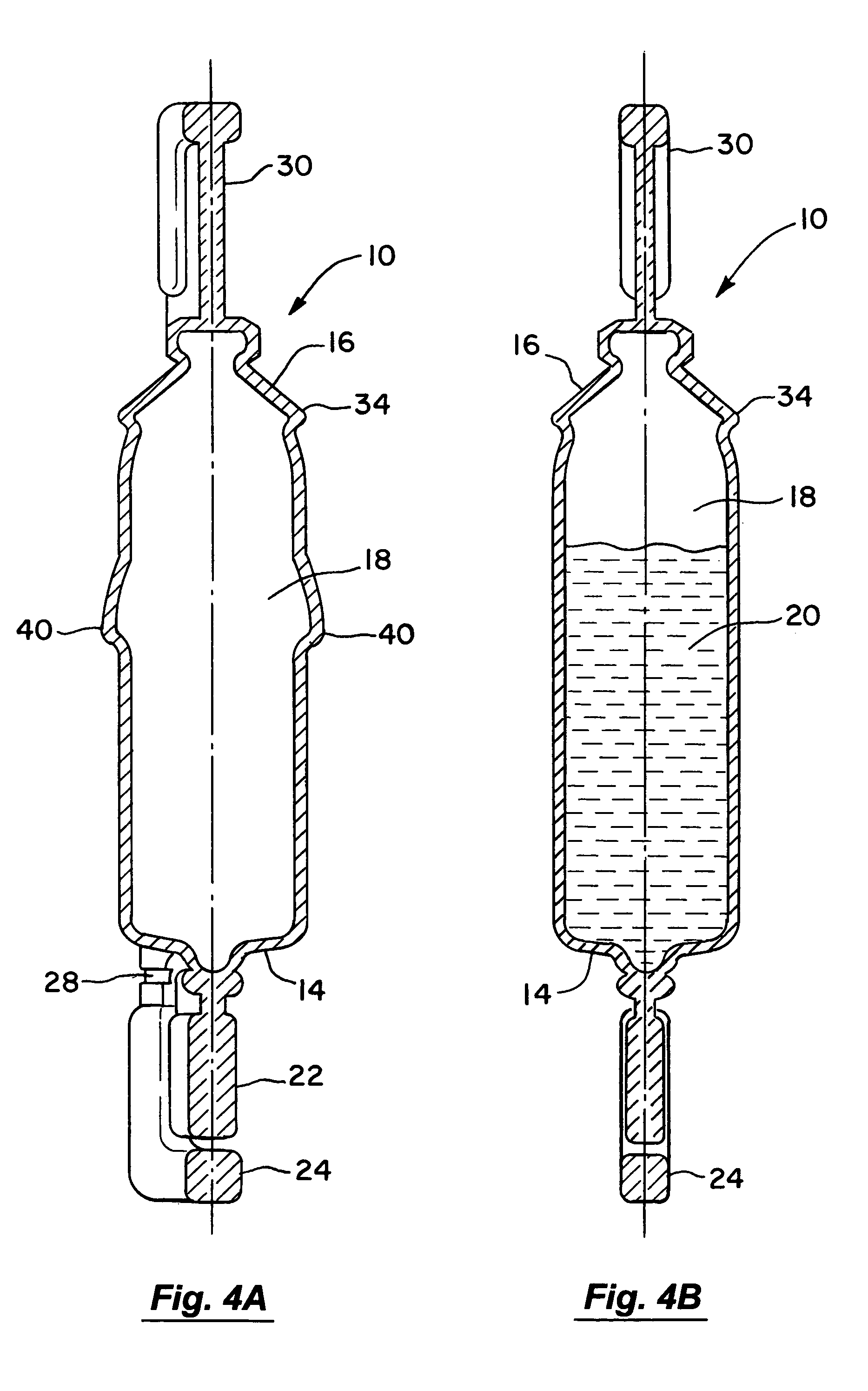
[0006]In one aspect, the ampoule may include a shroud that is coupled to the top end so that it is disposed about the top tab. In this way, the top tab is prevented from being removed until first moving or bending the shroud away from the top tab. Such a shroud is useful in ensuring the proper order of removal of the top and bottom tabs. For example, by preventing access to the top tab, a user may be trained to first remove the bottom tab. Once removed, the ampoule may then be placed into an aerosolization device. In so doing, the liquid remains within the ampoule because no vent has yet been provided. When the ampoule is within the aerosolization device, the shroud may be bent and the top tab removed to create the vent opening. Upon creation of the vent opening, the liquid flows into the aerosolization device where it is available for aerosolization.
[0009]In a further aspect, the ampoule may be provided with a large sealing surface that is configured to provide a seal with the aerosol generator. The large sealing surface is advantageous in that it leaves a relatively large, empty socket in the aerosolization device after the ampoule is removed. In this way, the aerosolization device may more easily be accessed during cleaning after the ampoule has been removed. The large sealing surface may conveniently be provided by tapering the bottom end to increase the surface area. In yet another aspect, the ampoule is provided with a relatively thick wall to reduce the chance of droplet spillage. For example, the ampoule body may be provided with a wall thickness of at least about 0.03 inches.

Problems solved by technology

Alternatively, the tabs may be crack tabs where material is not completely removed but the seal is broken.

Method used


Image

  • Fluid filled ampoules and methods for their use in aerosolizers
  • Fluid filled ampoules and methods for their use in aerosolizers
  • Fluid filled ampoules and methods for their use in aerosolizers

Examples


Embodiment Construction

[0022]The invention provides various ampoules used to store liquids that are to be atomized as well as techniques for transferring the stored liquids to an aerosolizer. The ampoules of the invention may conveniently include a variety of features to facilitate their use within various types of aerosolization devices. Such features may include, for example, features to insure their proper insertion into an aerosolization device, to insure proper operation of the ampoules when releasing the stored liquids, and to insure that the correct ampoule is being inserted into the aerosolization device.

[0023]The ampoules of the invention may be used with a wide variety of aerosolization devices that are configured to aerosolize a volume of liquid. Such aerosolizers may be of the type, for example, where a vibratable member is vibrated at ultrasonic frequencies to produce liquid droplets. Some specific, non-limiting examples of technology for producing fine liquid droplets is by supplying liquid ...


PUM


Abstract

A fluid filled ampoule comprises an ampoule body having a top end, a bottom end and a sealed interior containing a liquid. A top tab is coupled to the top end and is removable to create a drain vent in the top end. A bottom tab is coupled to the bottom end and is removable to create a drain opening in the bottom end. A movable shroud is coupled to the top end and is disposed about the top tab. The shroud is movable to permit access to the top tab.

Description

[0001]This application is a continuation application of U.S. Ser. No. 09 / 812,755, filed Mar. 20, 2001, the complete disclosures of which are herein incorporated by reference.BACKGROUND OF THE INVENTION[0002]This invention relates generally to the field of liquid aerosolization, and in particular to the management of liquids used in the aerosolization process. More specifically, the invention relates to ampoules containing liquids that are to be aerosolized.[0003]The ability to aerosolize or nebulize small liquid droplets is important to a variety of industries. Merely by way of example, many pharmaceuticals can now be delivered to the lungs in liquid form. Aerosolization is also a useful technique to dispense deodorizers, perfumes, insecticides or the like into the atmosphere.[0004]Aerosolizers or nebulizers typically utilize a supply of liquid that is contained in some type of reservoir, such as a container, canister, or the like. In this way, the liquid may be stored in a sealed e...

Claims


Application Information

Patent Timeline
Patent Type & Authority Patents(United States)
IPC IPC(8): B65D1/09A61M15/00B65D83/04B65D85/42A61J1/06B05B17/06
CPCA61J1/065A61M15/0028A61M15/0085A61M15/009A61M15/0031B65D1/095A61M2205/6045A61M2205/6054B65D2203/00Y10S215/03Y10S206/828A61J2205/10A61J2205/60B05B17/0607
Inventor LOEFFLER, JOSEPH P.POYNTER, RICHARD Q.RAPP, DAVIDKLIMOWICZ, MICHAEL
Owner NOVARTIS FARMA
Why Eureka
Eureka Blog
Learn More