
Multi-user detection method

Inactive Publication Date: 2006-04-18
MITSUBISHI ELECTRIC CORP
View PDF6 Cites 48 Cited by
  • Summary
  • Abstract
  • Description
  • Claims
  • Application Information

AI Technical Summary

Benefits of technology

[0013]A first aim of the invention is to propose a detection method and device which allow elimination of multi-user interference when there are multipath channels without requiring an explicit calculation of the attenuation coefficients, phase rotations and directions of arrival of the paths of the different users.
[0018](c) a step of eliminating interference from the cleaned antennae signals;
[0020]According to a first embodiment, the first plurality of coefficients comprises a first set of complex coefficients and a second set of complex coefficients and the filtered signals are subjected to a channel formation step in order to form signals of paths by means of the said first set, the said path signals then being linearly combined by means of the said second set in order to supply the said estimation of the signal transmitted, the coefficients of the first set being adapted so as to minimise a plurality of first error signals between a reference value of the transmitted signal and the said path signals, the coefficients of the said second set being adapted so as to minimise a second error signal between the said estimation and the said reference value.
[0023]According to a second embodiment of the invention, the first plurality of coefficients consists of a set of complex coefficients and the filtered signals are linearly combined by means of the said set in order to supply the said estimation of the signal transmitted, the coefficients of the said set being adapted so as to minimise an error signal between the said estimation and a reference value.
[0027]According to a second variant of the invention, the users are classified in order of received power and the interference is eliminated by subtracting one after another the contributions of the different users, commencing with the users with the highest received powers.

Problems solved by technology

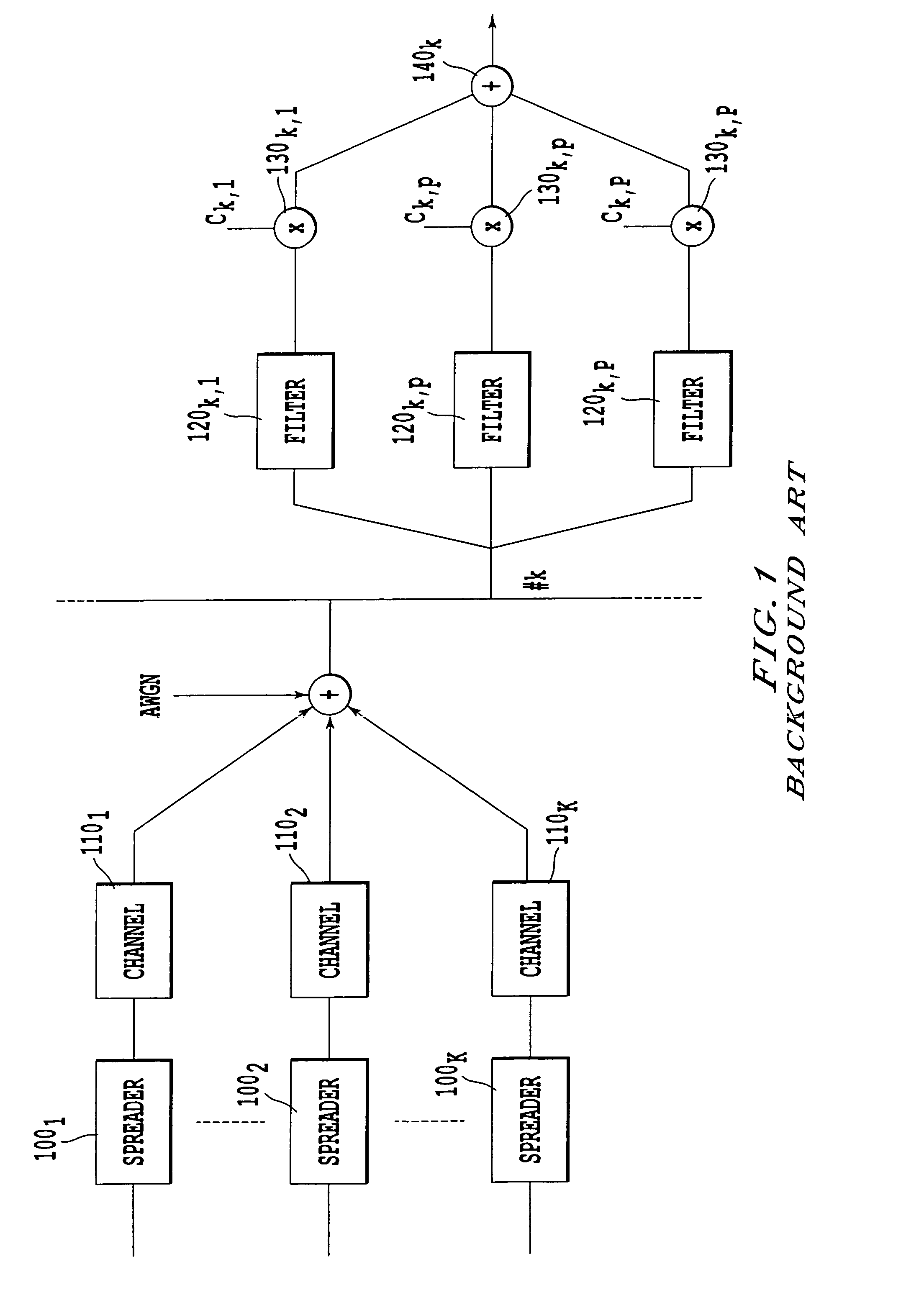
In practice, however, separation is not complete and leaves multipath interference which is also referred to as self-noise. FIG. 1 depicts schematically a DS-CDMA system with K users.
Moreover, when the number of users is high, close to the spread factor, the sum of the interferences of the different users, low if taken in isolation, can have very disturbing effects on detection.
When the channels are multipath, the situation is on the other hand much more complex since it is necessary to eliminate both the multipath interference and the multi-user interference.

Method used


Image

  • Multi-user detection method
  • Multi-user detection method
  • Multi-user detection method

Examples


second embodiment

[0085] it is considered that the phase difference remainders are negligible and therefore that the coefficients ci,k are essentially real.

[0086]There is then chosen:

ui,k=|ci,k| or ui,k=ci,k or ui,k=Re[ci,k]  (10)

[0087]where Re[.] represents the real part.

[0088]In the same way, the coefficients bl,i,k are considered to be pure phase differences. The terms wl,i,k can then be chosen so as to reconstruct the phase differences corresponding to the coefficients bl,i,k applied in (420k).

[0089]According to a first variant embodiment, there is then chosen:

[0090]According to a second variant of the invention, a linear regression is effected on the values ψl,i,k as described in French application FR-A-0011160 filed on 29 Aug. 2000 in the name of the applicant and incorporated here by reference. More precisely, for a given path i, the values {circumflex over (ν)}i,k and {circumflex over (φ)}i,k which minimise the mean square deviation J are sought:

[0091]J⁡(v^i,k,φ^i,k)=∑l=1L⁢(v^i,k+(l-1)·φ^i,k-...

fourth embodiment

[0123]FIG. 8a depicts a multi-user detection device according to the invention.

[0124]This embodiment extends the parallel elimination mode in the sense that it now includes a “multi-equalisation” function which will be explained below. The reference numbers indicated are the translations of those of FIG. 6 when they correspond to identical fictions. The device depicted in FIG. 8a nevertheless differs from the one in FIG. 6 in that it comprises a linear filter (805) upstream of the decision modules (810k). The purpose of this filtering is to take into account the outputs of the receivers of the first type or second type (800k) at different sampling times in the elimination of the interference. The filter (805) is a transverse linear time filter which fulfils a role equivalent to that of a conventional transverse linear equaliser when a single user is considered. Unlike the latter, however, the filter (805) is a matrix filter which operates on size vectors K and therefore uses matrice...

fifth embodiment

[0126]FIG. 9 depicts a multi-user detection device according to the invention.

[0127]This embodiment transposes the technique of equalisation by decision feedback (DF) in the multi-user context. The modules (900), (910), . . . (980) are modules identical to the modules (800), (810), . . . , (880) of FIG. 8, each module operating, as stated, on a vector with K components. The device comprises a precursor transverse filter (905) identical to the filter (805) and a postcursor filter (907) filtering the vector of the symbols ŝ′k at the output of the module (950). The output of the postcursor filter is subtracted (906) at the input of the decision module (910). The assembly consisting of the transverse filter (905) and the feedback filter (907) can, there too, be optimised according to a known technique, ZF or MMSE for example.

[0128]The postcursor filter (907) must be causal so as to ensure that there is no need to subtract the contribution of time samples not yet available at the time of...


PUM


Abstract

Multi-user detection method with elimination of interference between users, each user transmitting modulated data in the form of symbols on a transmission channel, each transmission channel (k) comprising at least one propagation path (i) and each propagation path arriving at an array of reception antennae (l) according to a direction of arrival (θi,k), the method comprising at least one sequence of steps for each user (k), each sequence comprising:(a) a reception step (600k,700k,800k,800,900) decomposing each antenna signal into filtered signals (xl,i,k) issuing from the different paths (i) of the said user (k) and combining the said filtered signals by means of a first plurality of coefficients (bl,i,k, ci,k) in order to form an estimation (zk) of the signal transmitted by the user;(b) a step of estimating (670k,770k,870k,870,970) the contribution ((xl,k)l=1 . . . L) of the user to the signals received by the different antennae from the said estimation of the signal transmitted and a second plurality of coefficients (ui,k, wl,i,k ) obtained from the said first plurality of coefficients;(c) a step of eliminating interference (680k′,780k,880k,880,980) subtracting from the antenna signals the contribution estimated at step (b) in order to obtain cleaned antenna signals;the cleaned antenna signals supplied by at least one first sequence being used as antenna signals by at least one second sequence.

Description

BACKGROUND OF THE INVENTION[0001]1. Field of the Invention[0002]The present invention concerns in general terms a multi-user detection method (MUD). More precisely, the present invention relates to an iterative method of eliminating interference between users (Multiple Access Interference or MAI). The present invention applies more particularly to mobile telephony in DS-CDMA mode (Direct Sequence—Code Division Multiple Access) that is to say to mobile telephony using a code division access mode with spectral spreading by direct sequences.[0003]2. Description of Related Art[0004]In a DS-CDMA mobile telephony system, the different users are separated by multiplying each symbol of the user by a spreading sequence peculiar to it, also referred to for this reason as the signature of the user, the different signatures ideally being chosen so as to be orthogonal. The spreading sequence frequency (chip rate) being greater than the frequency of the symbols, the signal transmitted by each use...

Claims


Application Information

Patent Timeline
IPC IPC(8): H03C7/02H04B1/707H04B7/005H04B7/08H04B7/26
CPCH04B1/7103H04B1/7117
Inventor MOTTIER, DAVID
Owner MITSUBISHI ELECTRIC CORP
Learn More