
Ultrasonic agitation-assisted development of resist layer of master stamper/imprinter

a technology of resist layer and ultrasonic agitation, which is applied in the direction of photomechanical equipment, instruments, cleaning using liquids, etc., can solve the problems of poor pattern replication fidelity, frequent surface staining of resist materials, and expensive servo-pattern writing equipment for writing servo patterns, etc., to improve image contrast and topographically patterned surface contrast.

Inactive Publication Date: 2006-04-18
SEAGATE TECH LLC
View PDF10 Cites 2 Cited by
  • Summary
  • Abstract
  • Description
  • Claims
  • Application Information

AI Technical Summary

Benefits of technology

"The present invention provides an improved method for forming a topographical pattern in a surface of a resist layer, which can be used in the manufacturing of a master for a magnetic stamper / imprinter. The method involves sequential steps of providing a substrate with a resist layer, exposing the resist layer to an energy beam to form a latent image, and contacting the resist layer with a liquid developing solution containing a solvent and ultrasonic energy. The resulting topographical pattern has improved contrast between projecting and recessed features. The invention also provides a structure comprising a substrate with a resist layer having a topographically patterned exposed upper surface with improved contrast between projecting and recessed features."

Problems solved by technology

Because of the locational precision needed, writing of servo patterns requires expensive servo-pattern writing equipment and is a time consuming process.
Disadvantageously, however, the above-mentioned resist materials frequently exhibit surface staining and poor pattern replication fidelity upon developing, including, inter alia, varying feature geometries and poor contrast between exposed and unexposed regions, attributed to very short development intervals, e.g., on the order of several seconds.
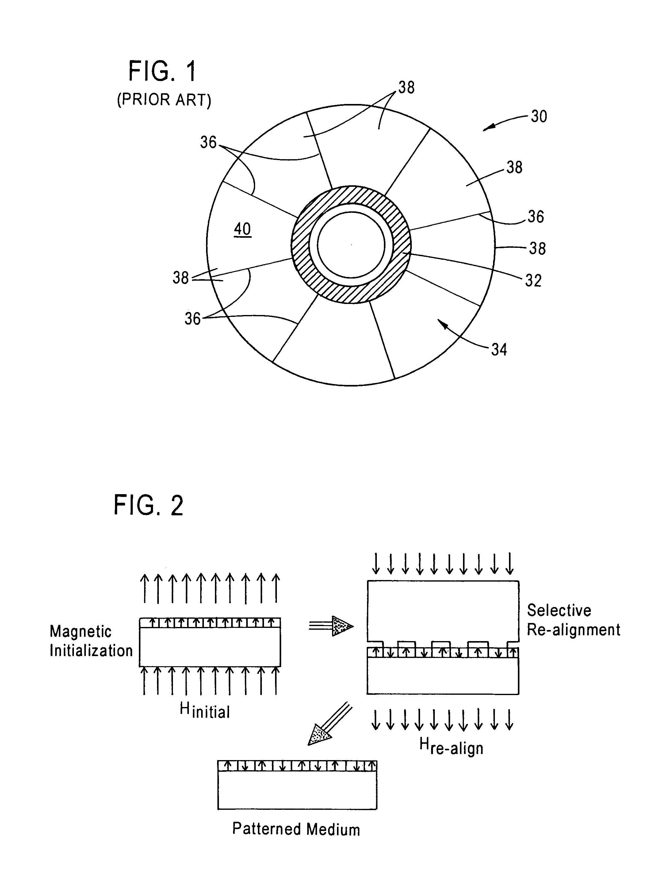
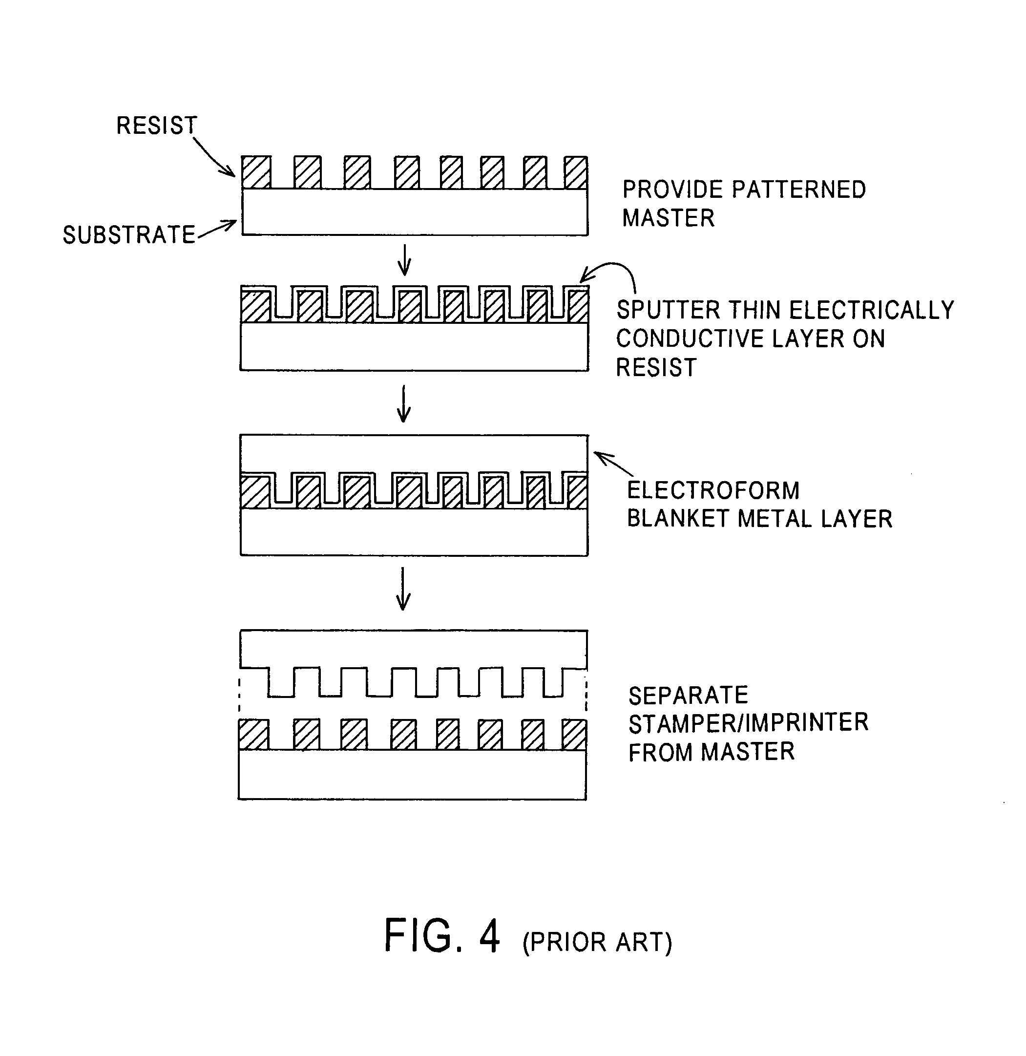
As a consequence, stampers / imprinters fabricated from “masters” manufactured according to conventional technology (such as described in FIG. 4) and involving short solvent developing intervals similarly exhibit poor pattern replication fidelity, i.e., varying feature geometries and poor contrast between exposed and unexposed regions.

Method used


Image

  • Ultrasonic agitation-assisted development of resist layer of master stamper/imprinter
  • Ultrasonic agitation-assisted development of resist layer of master stamper/imprinter
  • Ultrasonic agitation-assisted development of resist layer of master stamper/imprinter

Examples


example

[0060]A series of test specimens were prepared, each comprising a layer of a positive e-beam resist (Nippon Zeon ZEP 520A-7) on a metal substrate. Each specimen was then exposed to a scanned e-beam for creation of a latent image therein, followed by development of the latent image. Development times of the latent images in conventional n-amyl acetate (Nippon Zeon ZEP 520) solvent without ultrasonic agitation ranged from about 4 to about 8 sec., whereas development times (at room temperature) in a developer solution comprising a solvent comprised of 50 vol. % isopropyl alcohol (IPA) and 50 vol. % de-ionized (DI) water with ultrasonic agitation supplied thereto at 40 kHz and 185 W power ranged from about 15 to about 30 min. Microscopic analysis of the developed specimens indicated that those developed at the longer development times provided by the ultrasonic agitation of the developer solution exhibited improved contrast between projecting and depressed features, relative to the spec...


PUM

PropertyMeasurementUnit
frequencyaaaaaaaaaa
widthaaaaaaaaaa
widthaaaaaaaaaa

Abstract

A method of forming a topographical pattern in a surface of a resist layer, comprising sequential steps of:(a) providing a substrate having a surface;(b) forming a desired thickness resist material layer on the substrate surface;(c) subjecting selected areas of the surface of the resist layer to exposure to an energy beam to form therein a latent image of a desired topographical pattern to be formed therein;(d) contacting the surface of the resist layer with a liquid developing solution comprising a preselected solvent for developing the latent image into the desired topographical pattern while simultaneously supplying ultrasonic energy thereto, the combination of supplying the ultrasonic energy to the preselected solvent providing an increased developing interval and improved image contrast between the exposed and unexposed areas of the layer of resist material, relative to when the liquid developing solution does not comprise the preselected solvent and the ultrasonic energy is not supplied thereto.

Description

CROSS-REFERENCE TO PROVISIONAL APPLICATION[0001]This application claims priority from U.S. provisional patent application Ser. No. 60 / 392,832 filed Jun. 28, 2002, the entire disclosure of which is incorporated herein by reference.FIELD OF THE INVENTION[0002]The present invention relates to a method for increasing the contrast between exposed and unexposed regions of a resist layer, and to a method for making an improved “master” employed in a process of forming magnetic stampers / imprinters for use in performing rapid, cost-effective patterning, e.g., servo patterning, of magnetic and magneto-optical (MO) recording media in hard disk form.BACKGROUND OF THE INVENTION[0003]Magnetic and magneto-optical (MO) recording media are widely used in various applications, e.g., in hard disk form, particularly in the computer industry, for storage and retrieval of large amounts of data / information. Typically such media require pattern formation in the major surface(s) thereof for facilitating ope...

Claims


Application Information

Patent Timeline
Patent Type & Authority Patents(United States)
IPC IPC(8): G03C5/00
CPCG03F7/3014Y10S430/146Y10S430/143G11B5/855
Inventor FORMATO, CHRISTOPHER
Owner SEAGATE TECH LLC
Learn More