
Current limiting strategy

a current limit and current limit technology, applied in the direction of electronic commutation motor control, dynamo-electric converter control, starter details, etc., can solve the problems of thermal overload conditions, inapplicability of cascaded speed and current loops, torque loops, etc., and achieve simple low-cost implementation. simple and easy

Inactive Publication Date: 2006-04-11
DELPHI TECH INC
View PDF2 Cites 22 Cited by
  • Summary
  • Abstract
  • Description
  • Claims
  • Application Information

AI Technical Summary

Benefits of technology

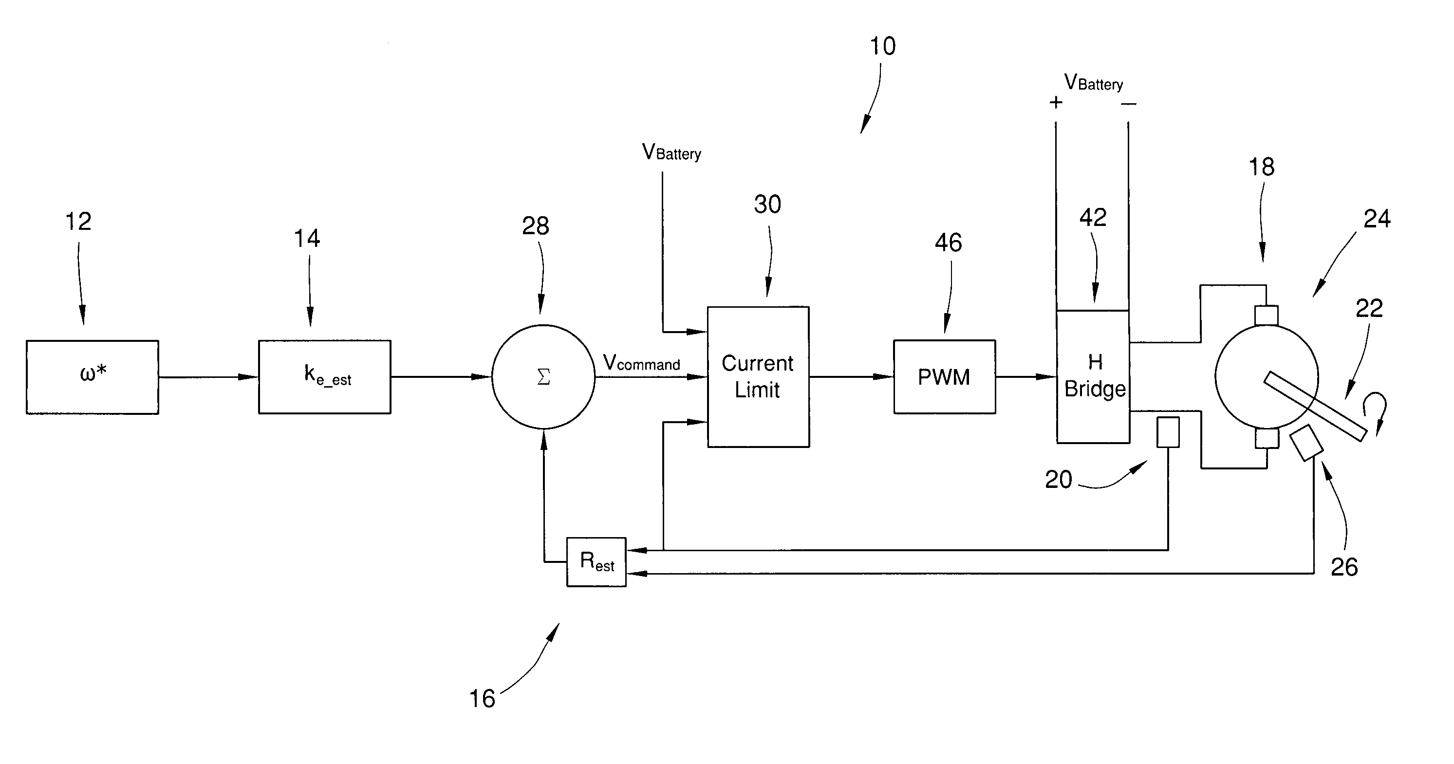
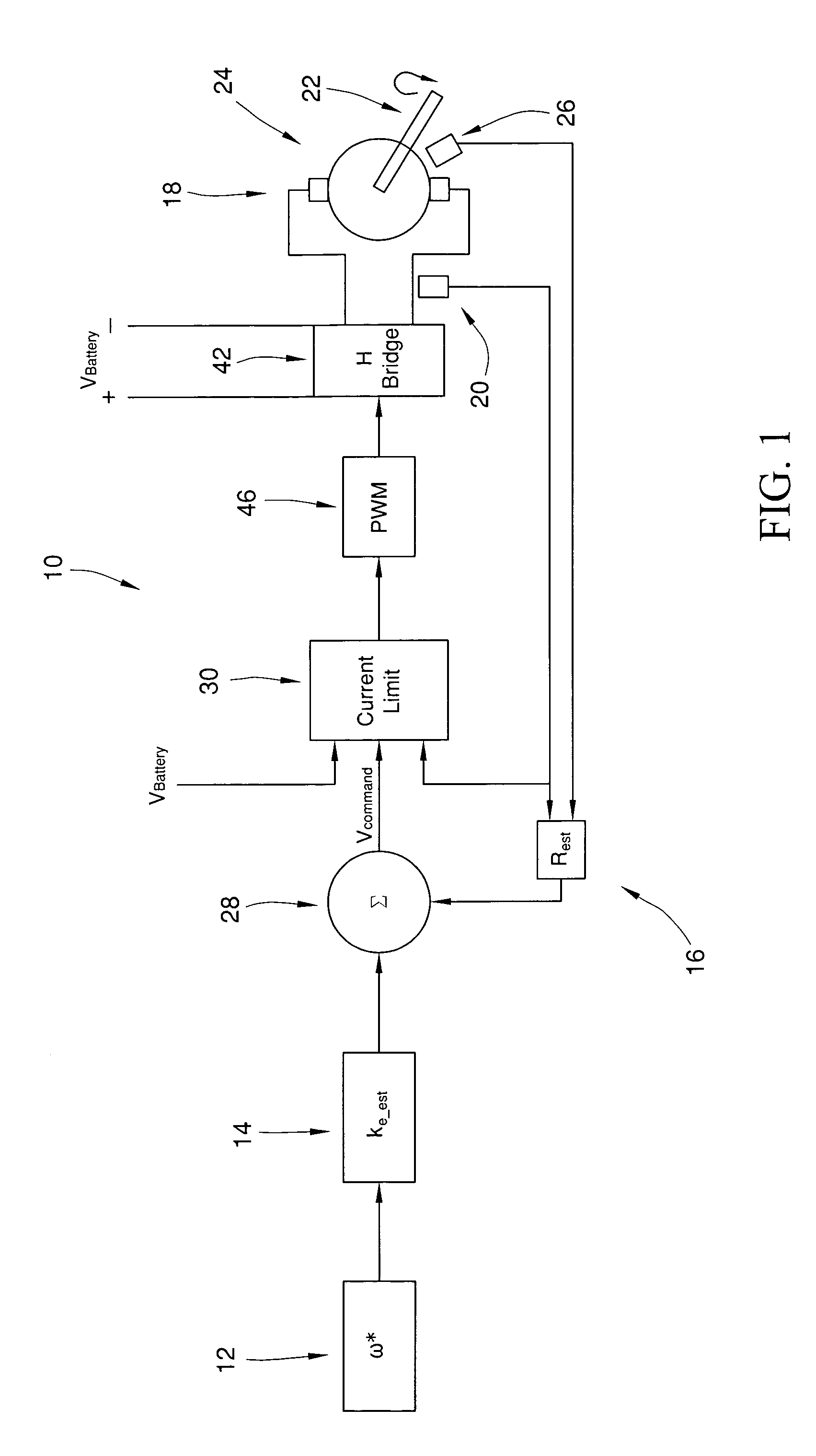
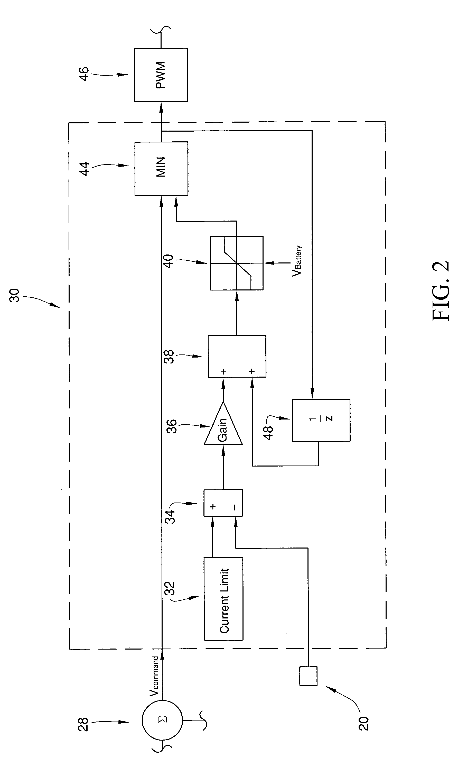
[0004]The method includes the step of rotating a motor shaft of the direct current motor with a controller by applying a first voltage across the direct current motor's terminals. The first voltage causes a first current to pass through armature windings of the direct current motor. The method also includes the step of selecting a maximum allowable amount of current to pass through the armature windings of the direct current motor. The maximum amount of current is selected to prevent undesirable over-current conditions, such as thermal overload as one example. The method also includes the step of sending a signal corresponding to a desired motor speed to the controller and converting this signal into a no-load voltage command during the operating step. The method also includes the step of setting a variable related to the estimated electrical resistance of the direct current motor to compensate for loads on the machine's shaft so that IR drop compensation control can be implemented. The method also includes the step of first computing a second voltage to replace the first voltage from the controller and determining whether the first current needs to be limited. Based on the current polarity and magnitude a new allowable voltage value is calculated that will limit the current to the desired current limit value. The invention provides simply and easily for four quadrant current control in applications where processing power is limited, no shaft position sensing is available, and a simple low cost implementation is desired.

Problems solved by technology

Thermal overload conditions can occur when current greater than the continuous rated value is directed through the motor drive for extended time periods.
Often, speed information is not available in the applications cited above due to cost reasons so a cascaded speed and current loop, or torque loop, is not applicable.
A control technique known as IR drop compensation is sometimes used to provide approximate speed control, but does not inherently provide any current protection.
If an operating mode occurs in which the wheels are unable to turn and the compensation is properly tuned, this control mode will lead to a large increase in current which requires some form of current limiting to properly protect the motor, power electronics and user.
However, these devices require the operator to take steps, such as replacing a fuse, in order to re-engage the motor drive.
There are operating conditions where this can lead to the loss of desired protective functionality to the user.
In addition, current protection can be provided in the electronic hardware by limiting the gate switching command periods; although this will not protect the drive over four quadrant operation.

Method used


Image

  • Current limiting strategy
  • Current limiting strategy
  • Current limiting strategy

Examples


Embodiment Construction

[0009]The invention provides a method for controlling current in a direct current motor 18 having a back emf constant ke and resistance Rs. The motor may have either a permanent magnet or a field winding to create the needed magnetic flux that determines in part the value of ke. The value of ke is generally constant for a magnet machine but can vary with a field wound machine. For the case of a field winding motor, the value of ke will change based on the value of the field current. A basic form of steady state speed control, IR drop compensation, can be created by recognizing that for a given desired speed the motor voltage must be equal to the sum of the current and Rs product and the emf voltage which is simply the product of ke and rotational speed. These values are not truly known to the controller and are designated ke—est and Rest. FIG. 1 is a simplified schematic diagram of the exemplary embodiment of the inventive method, wherein the steps are performable by a controller. T...


PUM


Abstract

The invention provides a method for controlling current in a direct current motor having a back emf constant (ke), which may be a function of field current if the direct current motor is a field wound machine, and motor resistance (Rs) in all 4 quadrants of operation. The method includes the step of rotating a motor shaft of the direct current motor with a controller by applying a first voltage across the direct current motor's terminals. The first voltage corresponds to a first value of current passing through the armature windings of the direct current motor. The method also includes the step of determining a maximum value of current to pass through the armature windings of the direct current motor. The maximum value of current is selected to prevent undesirable over current conditions, such as thermal overload as one example. The method also includes the step of receiving a signal corresponding to a desired motor speed (ω*) with the controller during the rotating step. The method also includes the step of first computing a second voltage to replace the first voltage from the controller after the receiving and determining steps and in view of the estimates of the back emf constant (ke<sub2>—< / sub2>est) and the armature resistance (Rest) of the direct current motor. The method also includes the step of limiting the second voltage, if necessary to limit the current, before replacing the first voltage based at least in part on a difference between the maximum value of current and the current polarity, a gain quantity, and the first value of current and voltage in order to dynamically control current during the operating step.

Description

FIELD OF THE INVENTION[0001]The invention relates to direct current motors and more specifically to a method for controlling the current passing through a direct current motor in all four quadrants of operation.BACKGROUND OF THE INVENTION[0002]In simplified direct current motor drives as are typically used in wheelchair and forklift applications, it can be necessary to protect the machine and electronics from thermal overload conditions as well as high current fault conditions as may occur if a winding short were to develop. Thermal overload conditions can occur when current greater than the continuous rated value is directed through the motor drive for extended time periods. Often, speed information is not available in the applications cited above due to cost reasons so a cascaded speed and current loop, or torque loop, is not applicable. Furthermore, the desired command to the vehicle is a speed command as opposed to a torque command which precludes using a torque, or current loop...

Claims


Application Information

Patent Timeline
IPC IPC(8): H02K17/32
CPCH02P6/002H02P6/182H02P25/021H02P23/0031H02P21/0025H02P6/28H02P25/024
Inventor WALTERS, JAMES E.
Owner DELPHI TECH INC
Learn More