
Fluid receptacle and filter system

a technology of receptacle and filter system, which is applied in the direction of liquid handling, carpet cleaning, separation process, etc., can solve the problems of dirt and debris, scratches and abrasions, and the finish of many vehicles is still susceptible to scratches and abrasions, so as to facilitate the retention of dirt particles, minimize the backflow of dirt, and minimize the surface area

Inactive Publication Date: 2006-04-11
LAMB DOUGLAS R
View PDF20 Cites 33 Cited by
  • Summary
  • Abstract
  • Description
  • Claims
  • Application Information

AI Technical Summary

Benefits of technology

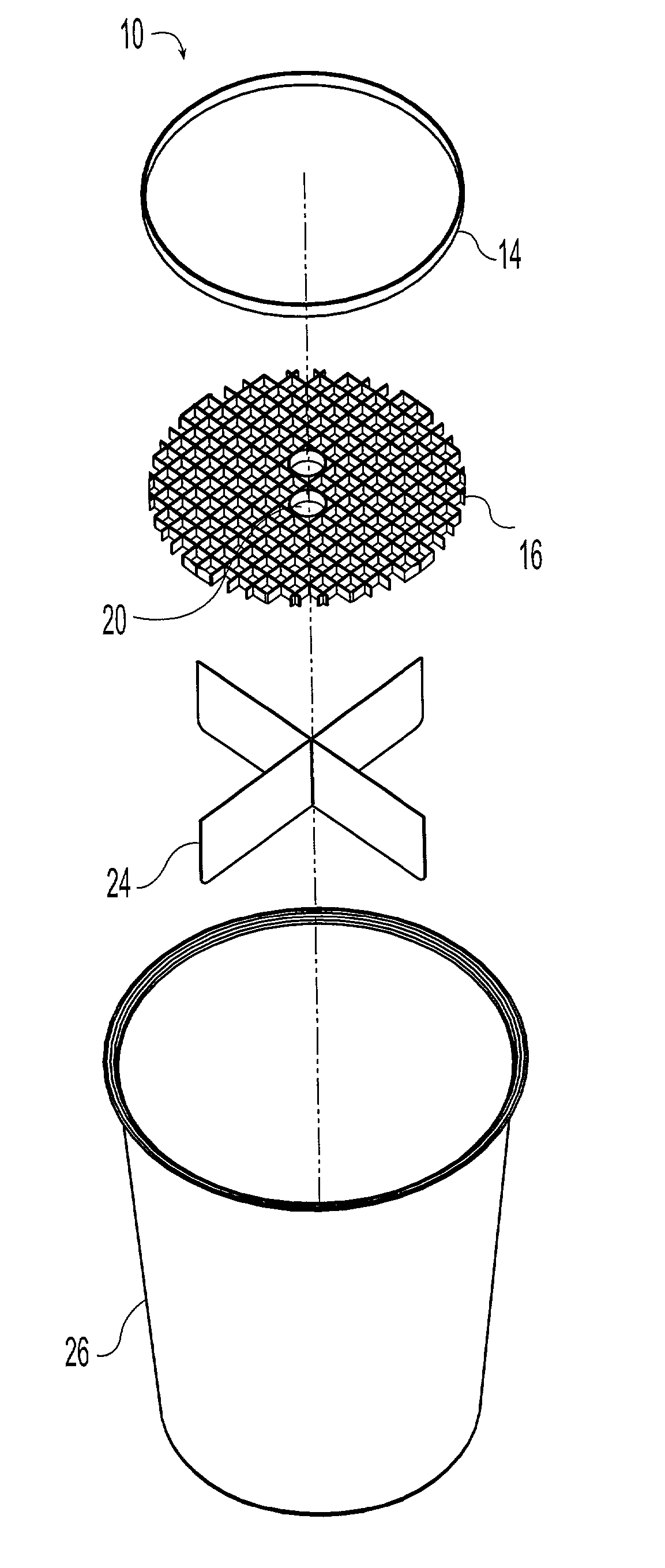
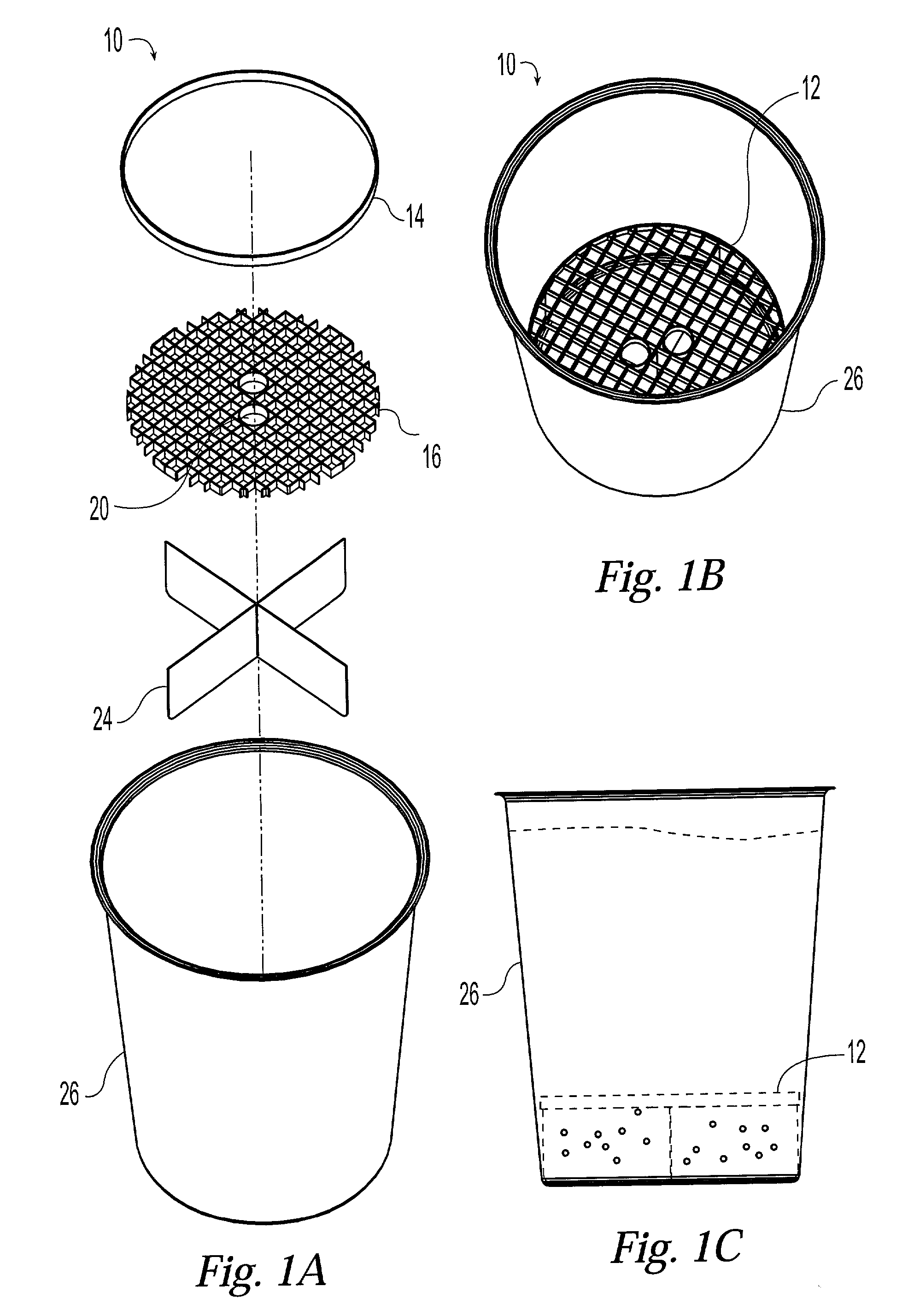
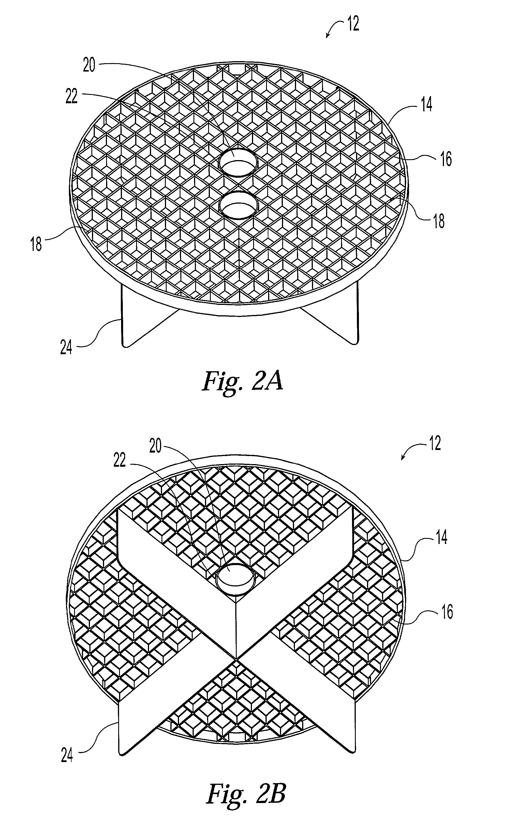
[0005]The filter component of the filter assembly has an upward facing side and a downward facing side and is made from a hard mesh, screen, or any other suitable screen-like material. Preferably, the upward facing side of the filter component includes crossbars that are tapered to minimize the surface area of said filter component. These tapered crossbars may also include barbs or other similar structures on the downward facing side of the filter assembly that facilitate the retention of dirt particles below the filter assembly.
[0007]In a preferred embodiment, the filter component includes at least one aperture that passes though the filter component and provides a means by which a user of the system may easily remove the filter assembly from the receptacle. Preferably, the aperture or apertures are defined by a band or ring of material that is either separate from the material of the filter component or formed from the material of the filter component.

Problems solved by technology

Despite the availability of modern paints and clear coating, the finish of many vehicles such as boats, automobiles, and motorcycles is still susceptible to scratches and abrasions.
One source of such scratches and abrasions can be the dirt and debris that often accumulates on the rags or mitts used to wash the exterior of these vehicles.
As the water becomes dirtier, the rag or mitt may actually pick up the grit or debris that has become suspended in the wash water or that has accumulated at the bottom of the bucket.
Thus, the wash rag or mitt is not effectively rinsed clean, and the grit and debris that is picked up by the rag from the dirty water is likely to be transferred back onto the exterior of the car, boat, or motorcycle where it can do significant damage to the vehicle's finish.

Method used


Image

  • Fluid receptacle and filter system
  • Fluid receptacle and filter system
  • Fluid receptacle and filter system

Examples


Embodiment Construction

[0016]The present invention provides a fluid receptacle and filter assembly for separating particles of gravel, dirt, grit and other relatively heavy debris from the wash water or other fluid contained in a bucket or other receptacle. In the context of this invention, “particle” refers to any and all debris that is heavy enough to fall out of suspension in a liquid or sink to the bottom of a bucket or other receptacle due to the effect of gravity.

[0017]As best shown in FIGS. 1A, 1B, and 2A, and according to a preferred embodiment, fluid receptacle and filter system 10 includes filter assembly 12, receptacle 26, and a lid for receptacle 26 (not shown). Filter assembly 12 further includes o-ring 14 and filter component 16 which further comprises crossbars 18, apertures 20, and baffles 24. In a preferred embodiment, o-ring 14 encircles filter component 16 and may be manufactured from plastic, rubber, or any other suitable material. Preferably, filter component 16 is manufactured from p...


PUM

PropertyMeasurementUnit
Shapeaaaaaaaaaa
Surface areaaaaaaaaaaa
Perimeteraaaaaaaaaa

Abstract

A system for separating particles from fluid which includes a receptacle for containing the fluid, a lid for covering the receptacle, and a filter assembly which includes a filter component shaped to fit the receptacle, an o-ring encircling the perimeter of the filter component for securing the filter assembly in the receptacle, and at least two baffles attached to the bottom of the filter component for reducing the motion of the fluid around and through the filter assembly.

Description

TECHNICAL FIELD[0001]This invention relates generally to filter systems that are useful for separating relatively heavy particles of debris that are suspended in solution from the solution itself, and specifically to a filtration system for separating relatively heavy particles of debris from dirty wash water contained in a receptacle such as a bucket.BACKGROUND OF THE INVENTION[0002]Despite the availability of modern paints and clear coating, the finish of many vehicles such as boats, automobiles, and motorcycles is still susceptible to scratches and abrasions. One source of such scratches and abrasions can be the dirt and debris that often accumulates on the rags or mitts used to wash the exterior of these vehicles. When a dirty wash rag or mitt is placed in a bucket of soapy water for rinsing, the grit and debris that has been picked up from the surface of the car or boat is transferred into the wash water. As the water becomes dirtier, the rag or mitt may actually pick up the gr...

Claims


Application Information

Patent Timeline
IPC IPC(8): A47L13/58B01D35/02B01D29/03
CPCB01D29/03
Inventor LAMB, DOUGLAS R.
Owner LAMB DOUGLAS R
Learn More