
Selectively cold worked hydraulic motor/pump shoe

a hydraulic motor and selective cold work technology, applied in the direction of machines/engines, liquid fuel engines, positive displacement liquid engines, etc., can solve the problems of difficult or impossible cracking of the crimping process, and achieve the effect of reducing the fracturing of the surface hardened face, improving the wear resistance of the auxiliary balance land, and simplifying the grinding

Inactive Publication Date: 2006-04-11
HONEYWELL INT INC
View PDF12 Cites 3 Cited by
  • Summary
  • Abstract
  • Description
  • Claims
  • Application Information

AI Technical Summary

Benefits of technology

The solution prevents cracking of the surface-hardened face, maintains the integrity of wear-resistant coatings, and increases wear resistance by providing a harder substrate for the coating, simplifying masking operations and enhancing the wear resistance of auxiliary balance lands.

Problems solved by technology

If the entire cylinder blank from which the shoe is formed were cold worked, the crimping process would be difficult or impossible to perform without cracking.

Method used


Image

  • Selectively cold worked hydraulic motor/pump shoe
  • Selectively cold worked hydraulic motor/pump shoe
  • Selectively cold worked hydraulic motor/pump shoe

Examples


Embodiment Construction

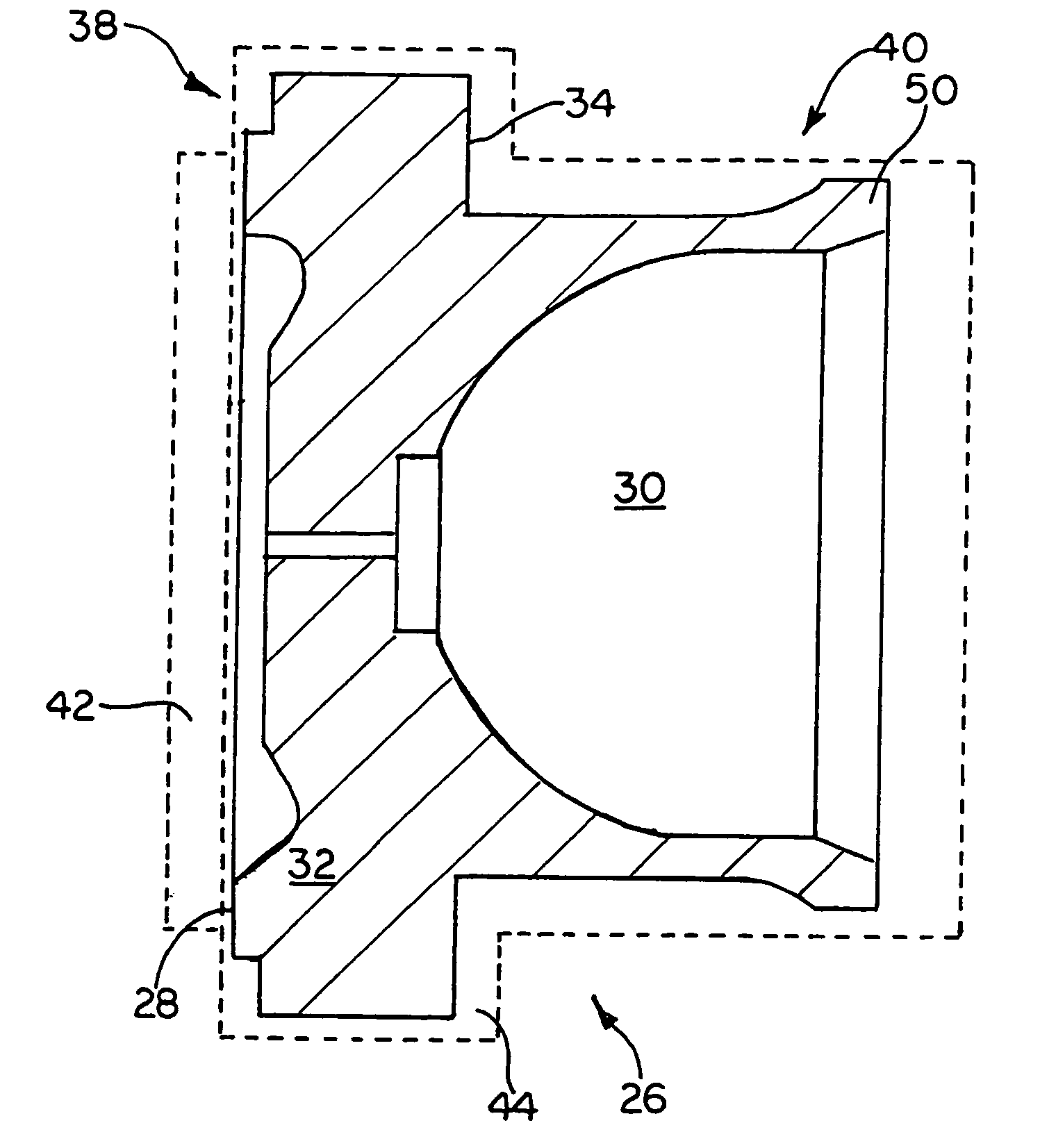
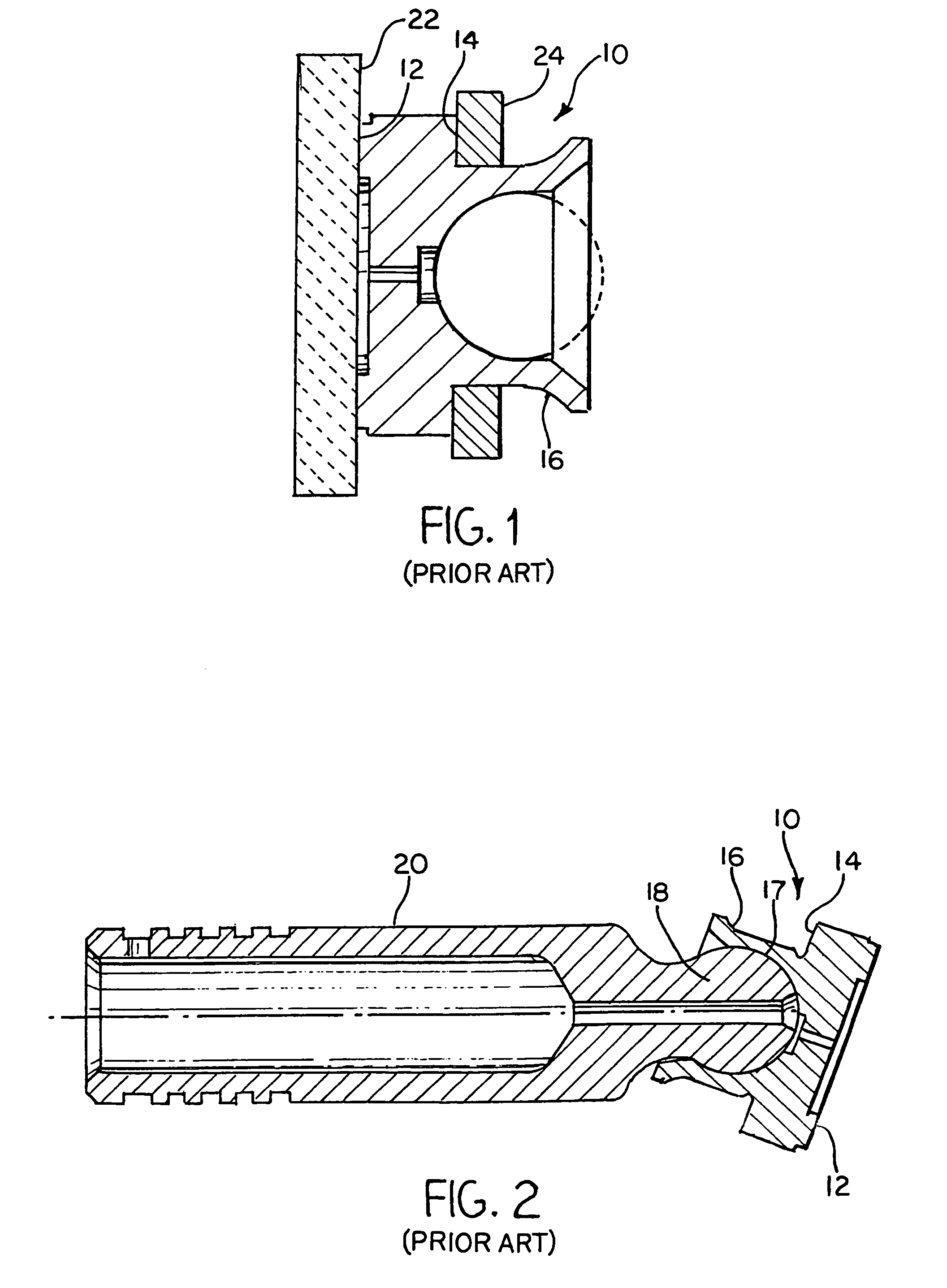
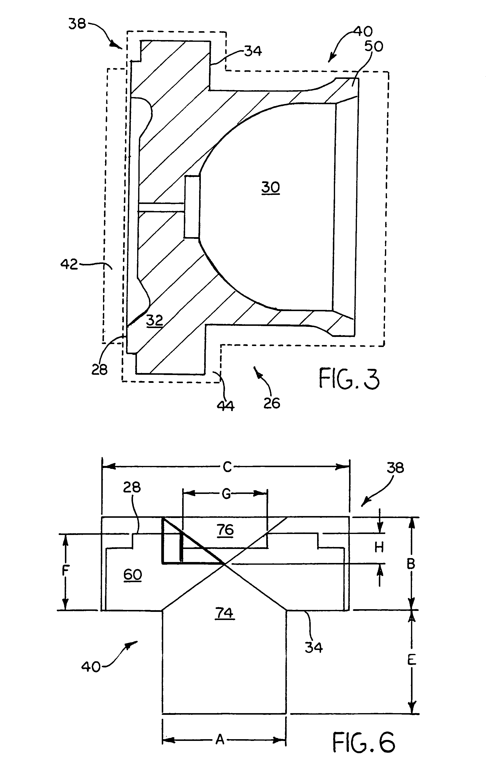
[0019]Referring now to the drawings and particularly to FIGS. 1 and 2, there is shown a piston shoe 10 of an axial piston pump or motor. FIG. 1 shows the piston skirt portion 16 or flange open to receive the rounded end of piston 20, while FIG. 2 shows that portion crimped about the annular or rounded piston head 18. The shoe 10 has a flat shoe wear surface 12 that contacts a cam plate 22. A back flange 14 of the shoe 10 also wears against an auxiliary cam plate 24. In order for the piston shoe 10 to operate within a fuel environment, the piston shoe 10 must be corrosion resistant, compatible with fuel, and provide the desired wear resistance. The piston shoe 10 is made of a cold workable cobalt based alloy which is compatible with fuel and provides corrosion resistance. The wear surface 12 which bears against the cam plate 22 and the back flange 14 which bears against the auxiliary cam plate 24 are provided with a thermal diffusion boride treatment which provides the desired wear r...


PUM

PropertyMeasurementUnit
temperatureaaaaaaaaaa
thicknessaaaaaaaaaa
wear resistantaaaaaaaaaa

Abstract

A method of manufacturing a wear resistant shoe (26) includes upsetting (46) one end portion (38) of cylindrical member to work harden that portion to a substantial depth, machining (48) the cylindrical member portion to finished dimensions and surface hardening (56) a face (28 or 34) of the machined cylindrical member portion. The cylindrical member may comprise rod stock of a diameter less than the greatest diameter of the finished shoe and be upset or swaged to axially reduce and radially increase the dimensions of the one end portion. A hollow region (30) is formed in an opposite rod stock end portion and the periphery (50) of the hollow region is crimped about a rounded end (18) of the piston (20). The cold work done during the swaging or forming process provides a foundation for hardened faces comprising balance (28) and auxiliary balance (34) lands, forms a crude shape of the shoe, and imparts work hardening and wear property improvements. The harder metal surface provides a foundation for subsequent surface hardening such as coating with TiN. The crimping process used to join the shoe to the piston imparts cold work to the skirt region of the shoe and enhances the wear resistance of the shoe. The cold heading step (46) may be omitted if a hardened rod stock is used, but the skirt should be annealed (66) prior to crimping to the piston.

Description

[0001]This application is a Divisional of application Ser. No. 09 / 896,261, filed on Jun. 29, 2001 U.S. Pat. No. 6,802,916, and for which priority is claimed under 35 U.S.C. § 120, the entire contents of which is hereby incorporated by reference.BACKGROUND OF THE INVENTION[0002]1. Field of the Invention[0003]The present invention relates to a process of making a wear resistant shoe of the type frequently employed to engage a swash-plate or moving cam surface in a pump or similar device, and the product resulting from that process.[0004]2. Description of the Related Art[0005]It is a fairly common practice to harden machinery parts that are subject to substantial wear. For example, pumps (and analogous motors) sometimes employ a plurality of pistons that are sequentially actuated by a off-axis rotating cam surface called a swash plate. Each piston has a shoe which is fixed to the piston by a ball and socket joint and has wear resistant face which engages the swash plate. U.S. Pat. No. ...

Claims


Application Information

Patent Timeline
Patent Type & Authority Patents(United States)
IPC IPC(8): F16D65/04B23P15/18B21K1/76B23P15/00F03C1/24F04B1/12F04B1/20F04B53/00
CPCB21K1/76B23P15/00F04B1/126Y10T29/49918Y10T29/49995
Inventor RATEICK, JR., RICHARD G.PORTOLESE, LARRY A.
Owner HONEYWELL INT INC
Learn More