
Cage valve with flow trim for reduced fracturing

a flow trim and valve body technology, applied in the field of cage valves, can solve the problems of valve trim failure, flow trim fracture, downstream equipment pressurization, etc., and achieve the effect of reducing fracturing

Active Publication Date: 2013-07-23
MASTER FLO VALVE
View PDF34 Cites 29 Cited by
  • Summary
  • Abstract
  • Description
  • Claims
  • Application Information

AI Technical Summary

Benefits of technology

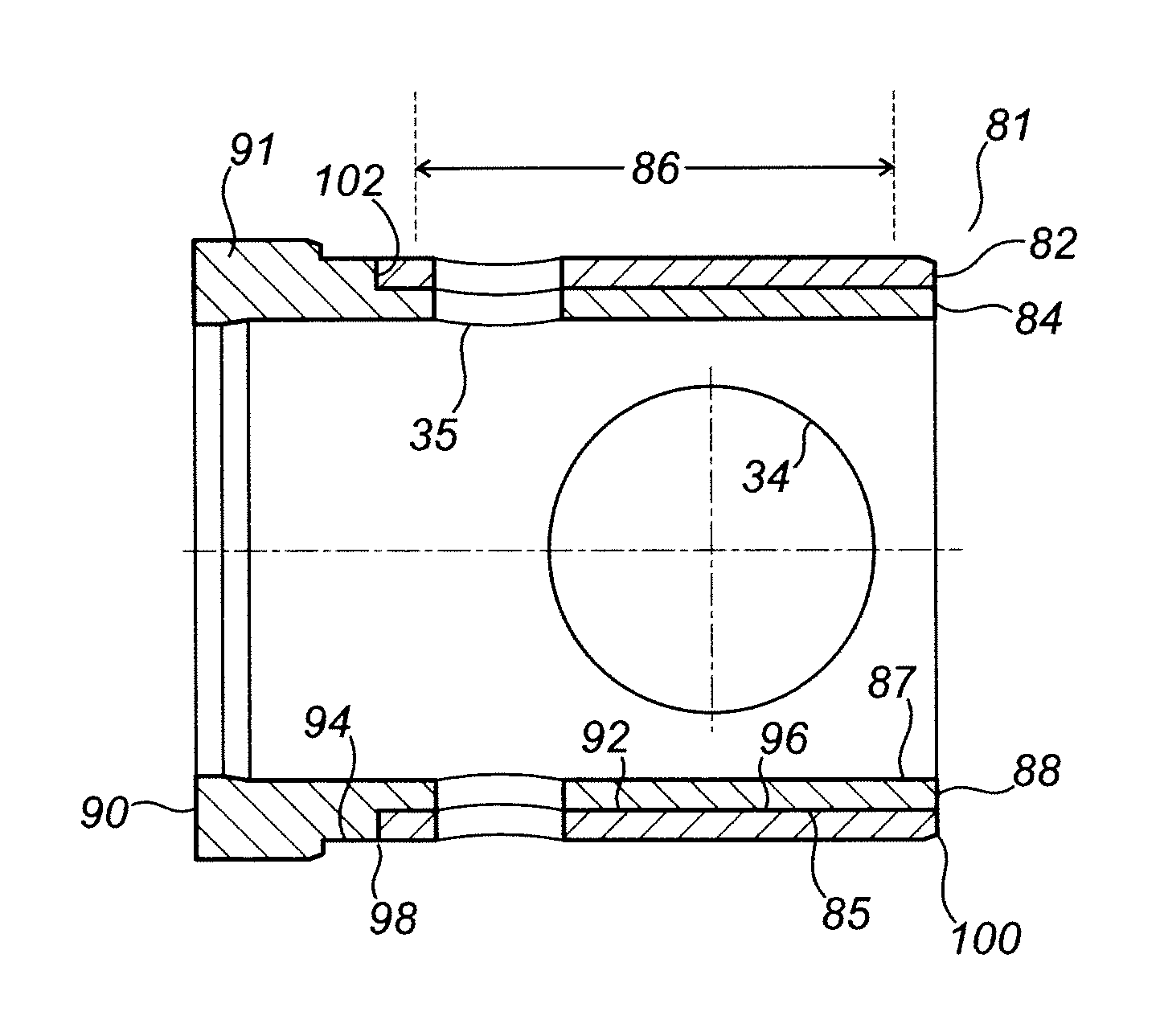
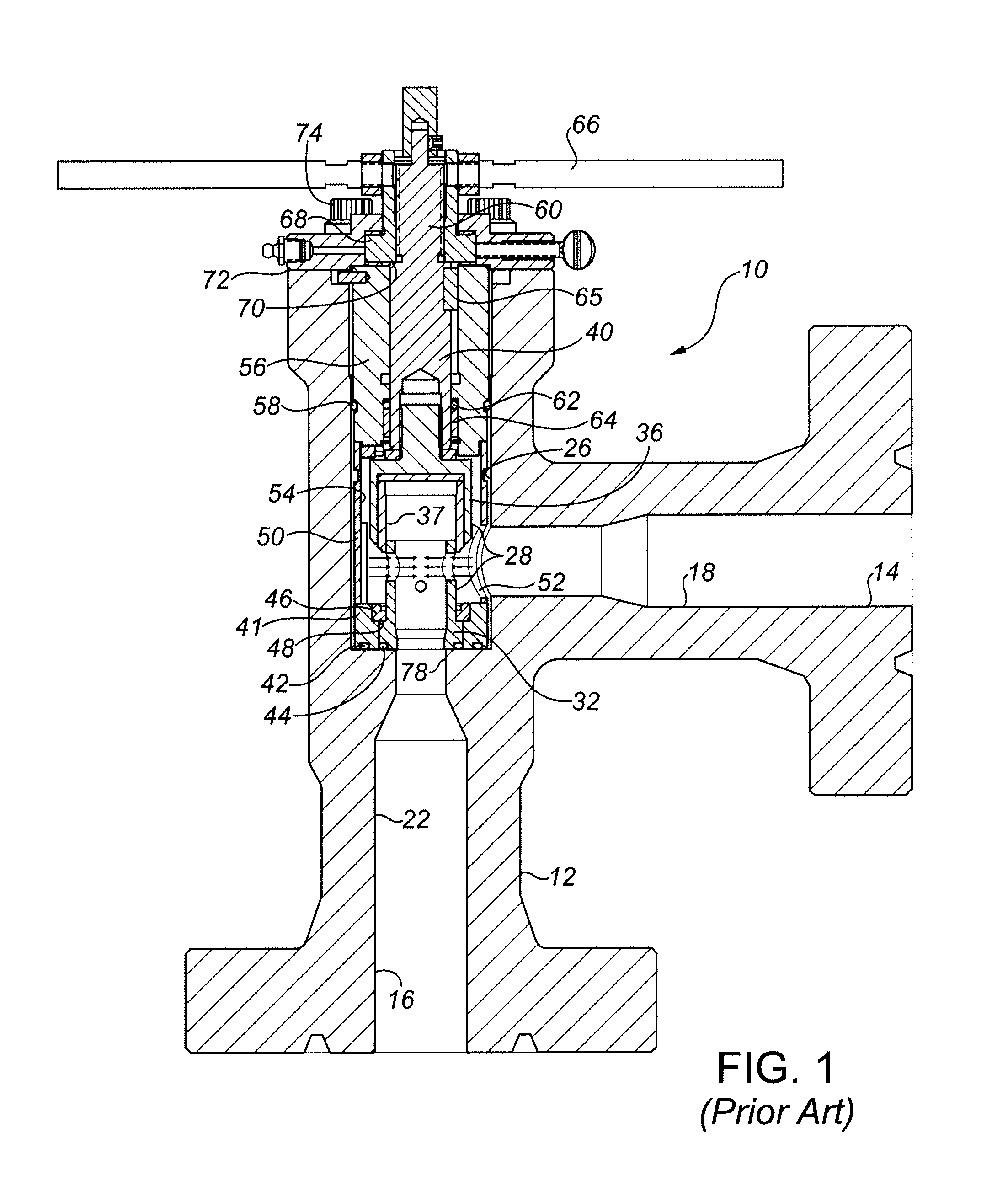
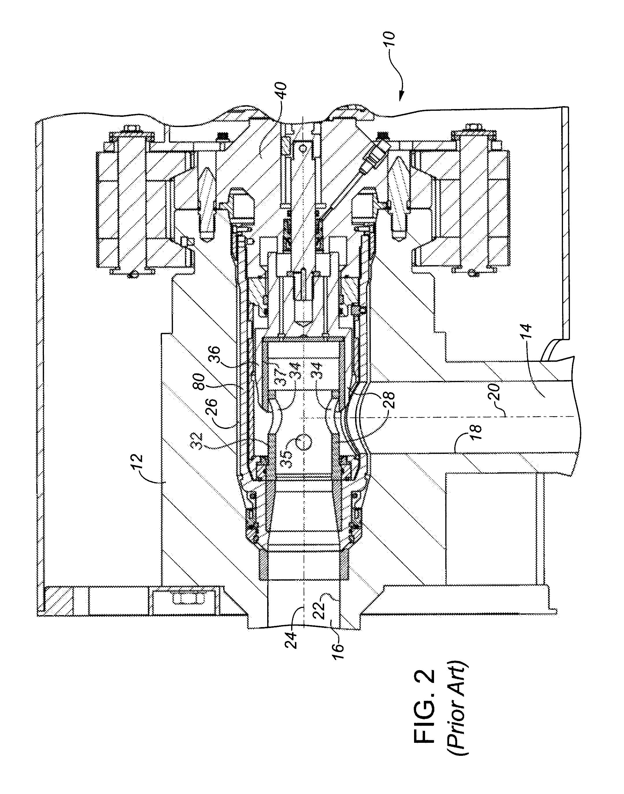
[0022]In one broad aspect, there is provided a valve having a fluid flow path extending therethrough which is to be restricted or closed. The valve includes a hollow valve body assembly having an inlet bore and an outlet bore substantially at right angles and a main bore which is an extension of the outlet bore and which communicates with the inlet bore. A flow trim is positioned in the main bore, the flow trim including a stationary tubular cage having a side wall, and an external cylindrical flow collar adapted for sliding movement along the side wall of the cage. The side wall of the cage forms an internal bore aligned with the outlet bore and has a ported portion between its ends formed with one or more flow ports. The external flow collar is adapted for movement between a closed position, wherein the one or more flow ports are fully covered by the external flow collar, and an open position, wherein each of the flow ports is fully or partially uncovered by the external flow collar. In this manner, fluid may enter the valve through the inlet bore, pass through the one or more flow ports at reduced pressure and continue through the outlet bore. A bonnet is disengagably connected with, and closes, an upper end of the valve body. A stem biases the external flow collar over the one or more flow ports. In order to reduce fracturing, the tubular cage is formed such that at least the ported portion includes a tubular outer cage member and a tubular inner cage member, the inner cage member and the outer cage member being formed from a tungsten carbide material, being concentrically aligned, having a length to span at least the ported portion, and being joined together by bonding at an interface formed between the inner cage member and the outer cage member. A ductile bonding material may be used at the interface, such as a solder, brazing or cement material. The ductile bonding material acts as a fracture arresting layer at the interface of the inner and outer cage members. In the event of a crack or fracture being initiated in the outer cage member, the ductile bonding material layer prevents the crack from propagating through the inner cage member.
[0030]Also provided are components of the valve, including the flow trim components and the retrievable valve components adapted as a removable insert assembly for sub-sea applications. There is also provided a method of reducing fracturing of the flow trim of a valve of a cage with external sleeve flow trim design.

Problems solved by technology

A problem that has produced many production interruptions both with surface and sub-sea facilities is the failure of valve trim due to fracture and cracking.
The common causes of this fracture are foreign debris moving through the flow line into the valve with sufficient mass and velocity to damage or fracture the valve trim.
High vibration and / or excessive side loads may also result in fracture of the flow trim.
Fractures or cracking of the flow trim may be extreme, causing catastrophic failure of the choke valve, which results in over pressurization of the downstream equipment or damage to the well formation due to excessive flow.
However, as the hardness grade of tungsten carbide is increased, the susceptibility to fracture also increases.
There have been a number of attempts at solutions to mitigate the damage caused by foreign debris; however, many of these attempts have resulted in a trade off to the potential wear capabilities of the choke trim.
Concentrations in the order of 12-15% have resulted in improved toughness of the tungsten carbide matrix; however, the volume of binder in the concentration results in a matrix with lower hardness and consequently substandard erosion characteristics.
This results in rapid wear to the flow trim resulting in costly production interruptions for valve maintenance or in the sub-sea applications, a high valve retrieval cost to facilitate maintenance.
However, the internal plug design has proven inferior for erosion resistance when compared to the external sleeve (flow collar) choke valve designs.
In the latter type of choke valves, the wear is extreme at the port areas between the external sleeve and the internal cage.
Using a steel sleeve over a tungsten carbide insert, as is done with the cage with internal plug design, would result in accelerated erosion.
An internal stainless steel sleeve will not only accelerate erosion to the cage bore, but would also result in tension loads being placed on the tungsten carbide outer sleeve.
The stress resulting from this arrangement would cause the tungsten carbide component to fracture.
In sub-sea wellheads, maintenance cannot be performed manually.

Method used


Image

  • Cage valve with flow trim for reduced fracturing
  • Cage valve with flow trim for reduced fracturing
  • Cage valve with flow trim for reduced fracturing

Examples


Embodiment Construction

[0037]As used herein and in the claims, the word “comprising” is used in its non limiting sense to mean that items following the word in the sentence are included and that items not specifically mentioned are not excluded. The use of the indefinite article “a” in the claims before an element means that one of the elements is specified, but does not specifically exclude others of the elements being present, unless the context clearly requires that there be one and only one of the elements.

[0038]The flow trim and cage component may be used in any external sleeve (flow collar) and inner cage valve design, and not merely in the valves of the type illustrated in FIGS. 1 and 2. For example, the cage component may be adapted for use with other known external sleeve inner cage valves, for example cage valves in which the cage component is fitted at or into the outlet of the valve, for example by threading. The cage component may be adapted for use in external sleeve inner cage valves in whi...


PUM

PropertyMeasurementUnit
inner diameteraaaaaaaaaa
pressureaaaaaaaaaa

Abstract

Cage valve, flow trim components and methods for reduced fracturing of flow trim. The valve is of the type having flow trim arranged across an inlet bore and aligned with an outlet bore, and including a stationary tubular cage and an external cylindrical flow collar slidable along the side wall of the cage to cover or uncover one or more flow ports in the cage side wall. The tubular cage is formed such that, at least in the ported portion in which the flow ports are formed, the cage includes a tubular outer cage member and a tubular inner cage member, the inner cage member and the outer cage member being formed from a tungsten carbide material, being concentrically aligned, having a length to span at least the ported portion, and being joined together by bonding at an interface formed between the inner cage member and the outer cage member.

Description

CROSS REFERENCE TO RELATED APPLICATIONS[0001]This application claims priority from U.S. Provisional Patent Application No. 61 / 297,652 filed Jan. 22, 2010, which is incorporated by reference in its entirety to the extent that there is no inconsistency with the present disclosure.BACKGROUND OF THE INVENTION[0002]This invention relates to a cage valve for reduced fracturing, to flow trim components, and to a method of reducing fracturing of the flow trim in the cage valve.[0003]A choke valve is a throttling device commonly used as part of an oil or gas field wellhead. It functions to reduce the pressure of the fluid flowing through the valve. Choke valves are placed on the production “tree” of an oil or gas wellhead assembly to control the flow of produced fluid from a reservoir into the production flow line. They are used on wellheads located on land and offshore, as well as on wellheads located beneath the surface of the ocean. Choke valves common to oil and gas field use are general...

Claims


Application Information

Patent Timeline
Patent Type & Authority Patents(United States)
IPC IPC(8): F16K3/24
CPCF16K3/24F16K27/041Y10T29/49405Y10T137/86734Y10T137/7668Y10T137/86759Y10T137/7036
Inventor BOHAYCHUK, LARRY J.MCNEILL, MARK K.
Owner MASTER FLO VALVE
Learn More