
Method for calibrating a mathematical model

Inactive Publication Date: 2006-04-04
VISTEON GLOBAL TECH INC
View PDF7 Cites 54 Cited by
  • Summary
  • Abstract
  • Description
  • Claims
  • Application Information

AI Technical Summary

Benefits of technology

[0007]The present invention overcomes the disadvantages of the prior art approaches by providing an improved method for accurately modeling the characteristics of a component.

Problems solved by technology

Calibrating the model based on this “strain gauge method” is subject to many inaccuracies.
Strain gauge size, direction, and placement are key contributors to inaccuracy.
Strain gauges are sometimes difficult to install on certain surfaces with high stress concentrations (fillet, hole, etc.) and sometimes impractical for use in measuring strain that is induced under certain circumstances (e.g., high strain gradient).
Since strain gauges measure strain at discrete points, poor selection of the strain gauge location can contribute to inaccuracy.
Extrapolation of strain gauge results on a three dimensional part with odd geometry can also result in an inaccurate model.
In addition, strain gauge instrumentation of larger parts can take up substantial amounts of engineer and technician time.

Method used


Image

  • Method for calibrating a mathematical model
  • Method for calibrating a mathematical model
  • Method for calibrating a mathematical model

Examples


Embodiment Construction

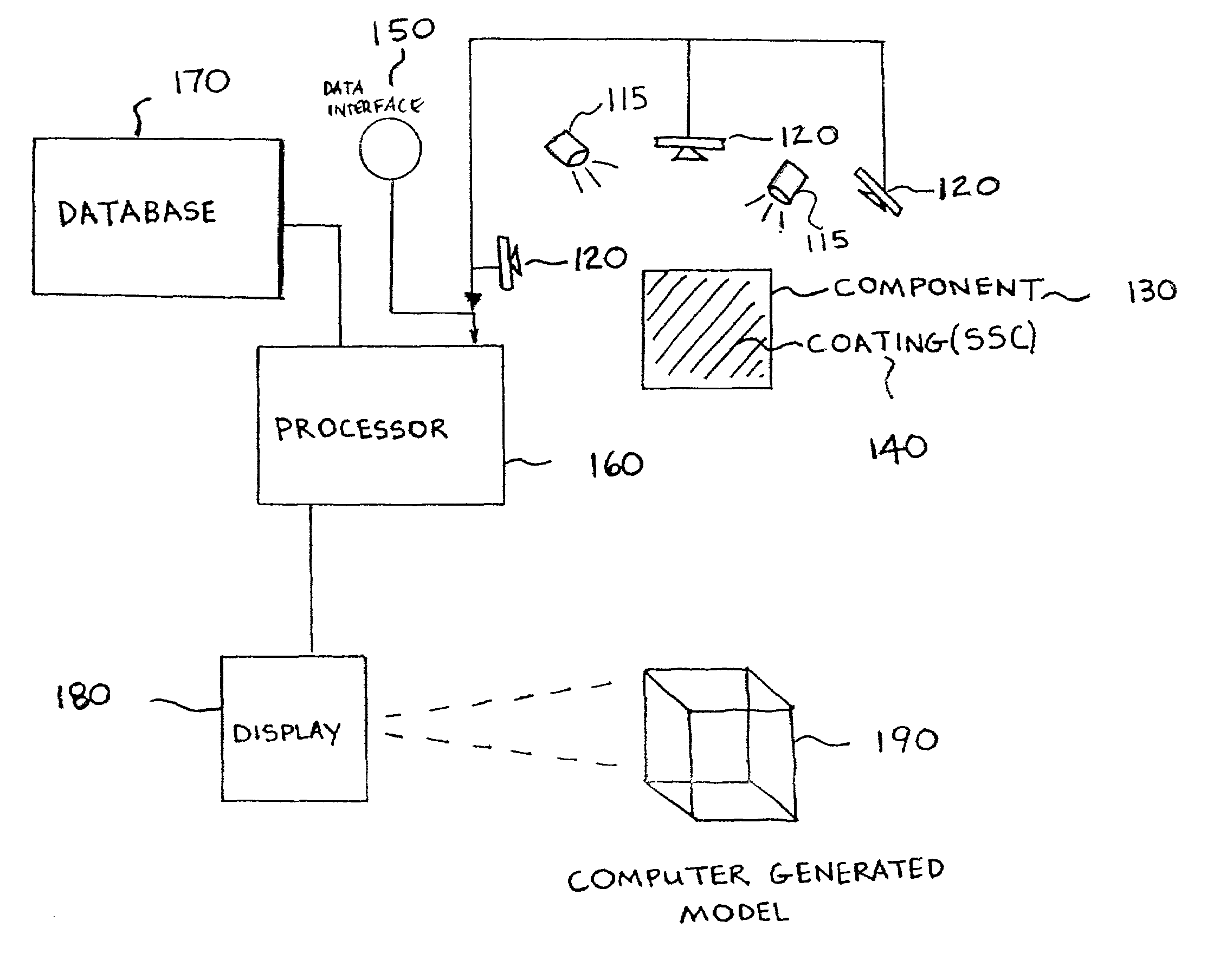
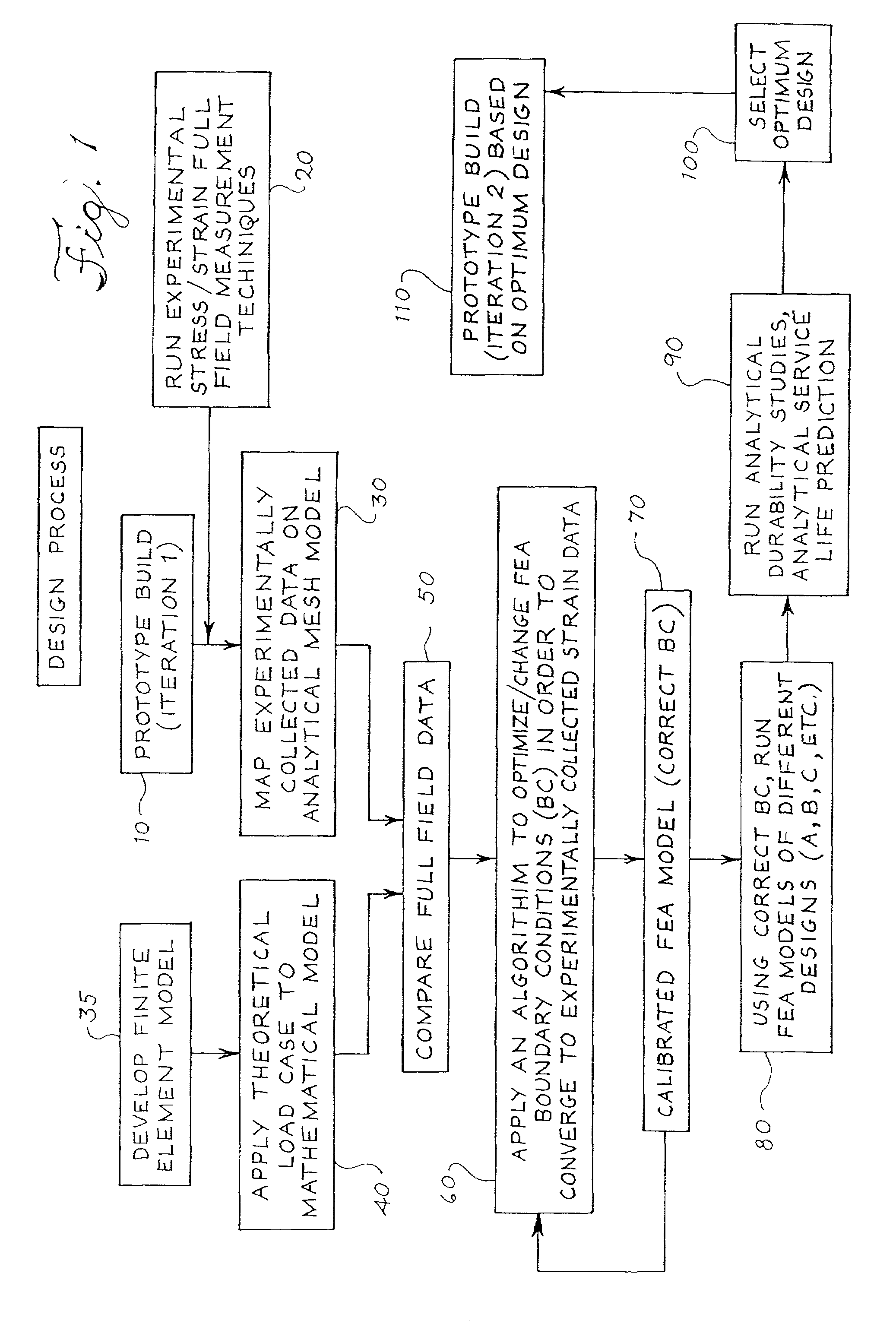
[0015]Referring now to the drawings, FIG. 1 shows a preferred embodiment of the method for calibrating a mathematical model, as well as optimizing the design of a component.

[0016]Referring to FIG. 1, the first step 10 requires building a prototype of the physical component to be subjected to analysis. This prototype of a component is restricted only by a manufacturer's imagination and needs. In other words, it is contemplated that the following method for optimizing a mathematical model is not restricted by the size or shape of a component.

[0017]Step 20 involves running physical strain tests on the prototype component of step 10 in order to develop a full field measurement. A full field measurement reflects measurement of the component at continuous points when the component is subjected to stress or strain. Several full-field measurement techniques exist including, but not limited to, moire interferometry, geometric moire, SPATE, speckle methods, holographic interferometry, brittle...


PUM


Abstract

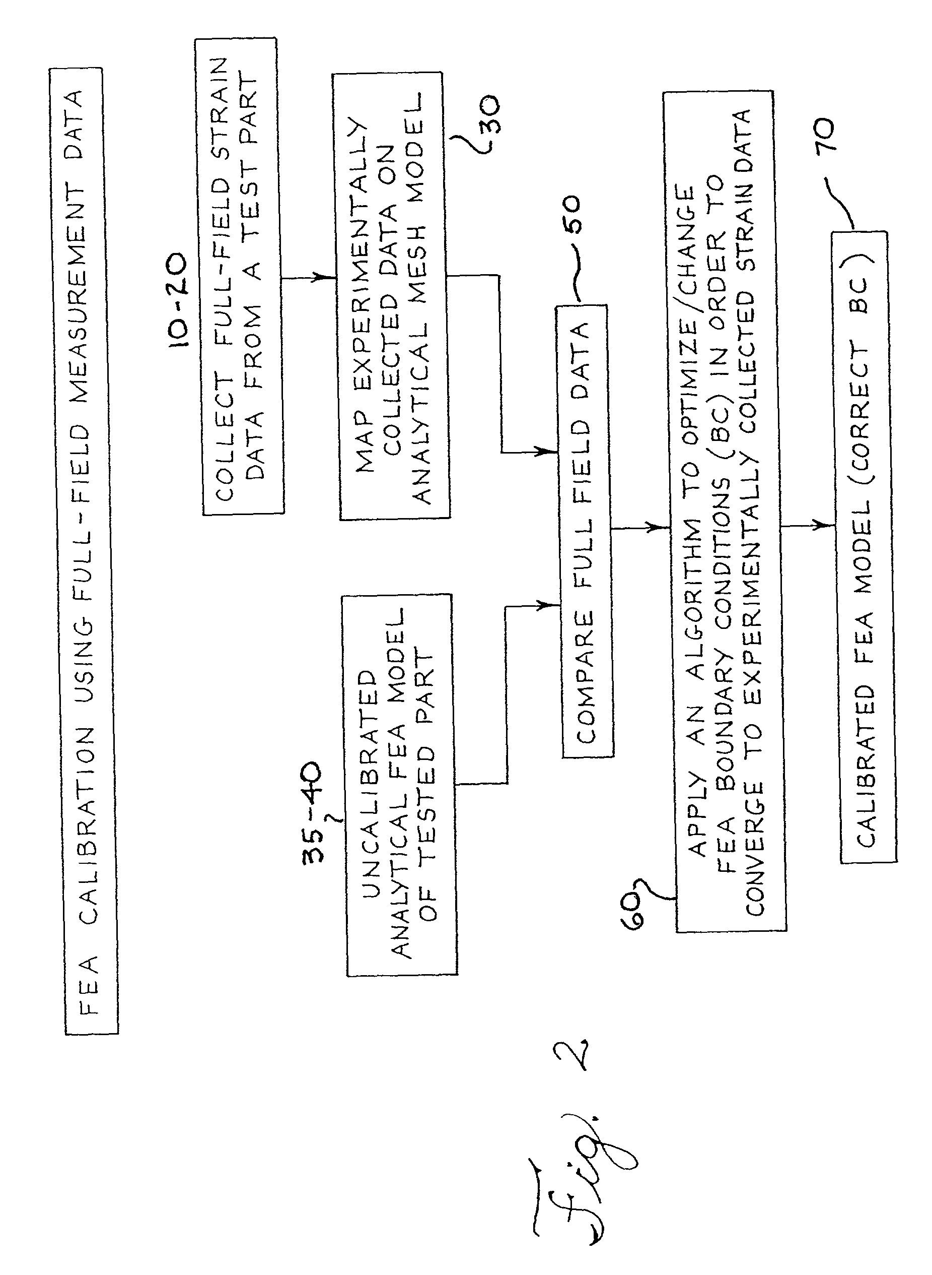
A method is disclosed for calibrating a mathematical model of a component using prototype full-field experimentally collected deformation / strain data. Specifically, the method involves obtaining actual experimental field data using strain sensitive coating material and then mapping said data on a CAD mesh model. The analytical mesh model is then compared to a finite element model that is based on theoretical values referred to as boundary conditions. The finite element model boundary conditions are then calibrated to reflect the values derived from the experimental field measurements. Once calibrated, the model can be used to optimize design of components.

Description

CLAIM FOR PRIORITY[0001]The present application claims priority from U.S. Provisional Application Serial No. 60 / 251,964, filed Dec. 7, 2000, which is fully incorporated herein.FIELD OF THE INVENTION[0002]The present invention generally relates to component design. In particular, the invention relates to a more accurate and efficient method of modeling components.BACKGROUND OF THE INVENTION[0003]The current preferred method for optimizing the design of components is by the use of Computer Aided Engineering (“CAE”). Traditional CAE methods typically utilize finite element analysis (“FEA”), which in turn is based on computer models of the part.[0004]Currently, CAE methods typically rely on theoretical mathematical models run through a computer simulation. The results of the analysis are only as accurate as the model. Accuracy of the model is typically a function of the time, effort and skill an engineer puts into creating the model. Model accuracy is also dependent on the accuracy and ...

Claims


Application Information

Patent Timeline
IPC IPC(8): G06G7/48G06F17/50G06T15/04G06T17/20
CPCG06F17/50G06T17/20G06T15/04G06F30/00
Inventor EL-RATAL, WISSAM H.
Owner VISTEON GLOBAL TECH INC
Learn More