
Compensating for drift and sensor proximity in a scanning sensor, in color calibrating incremental printers

Active Publication Date: 2006-04-04
HEWLETT PACKARD DEV CO LP
View PDF11 Cites 20 Cited by
  • Summary
  • Abstract
  • Description
  • Claims
  • Application Information

AI Technical Summary

Benefits of technology

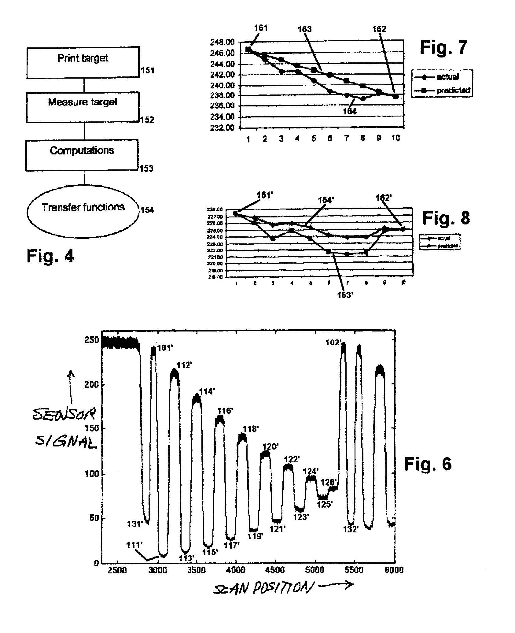
[0038]In particular, by scanning a tonal reference, together with the pattern—in the same scanning step—this aspect of the invention is able to make a real-time adjustment to the sensor response. The sensor response therefore can drift without impairing the accuracy of the color calibration.
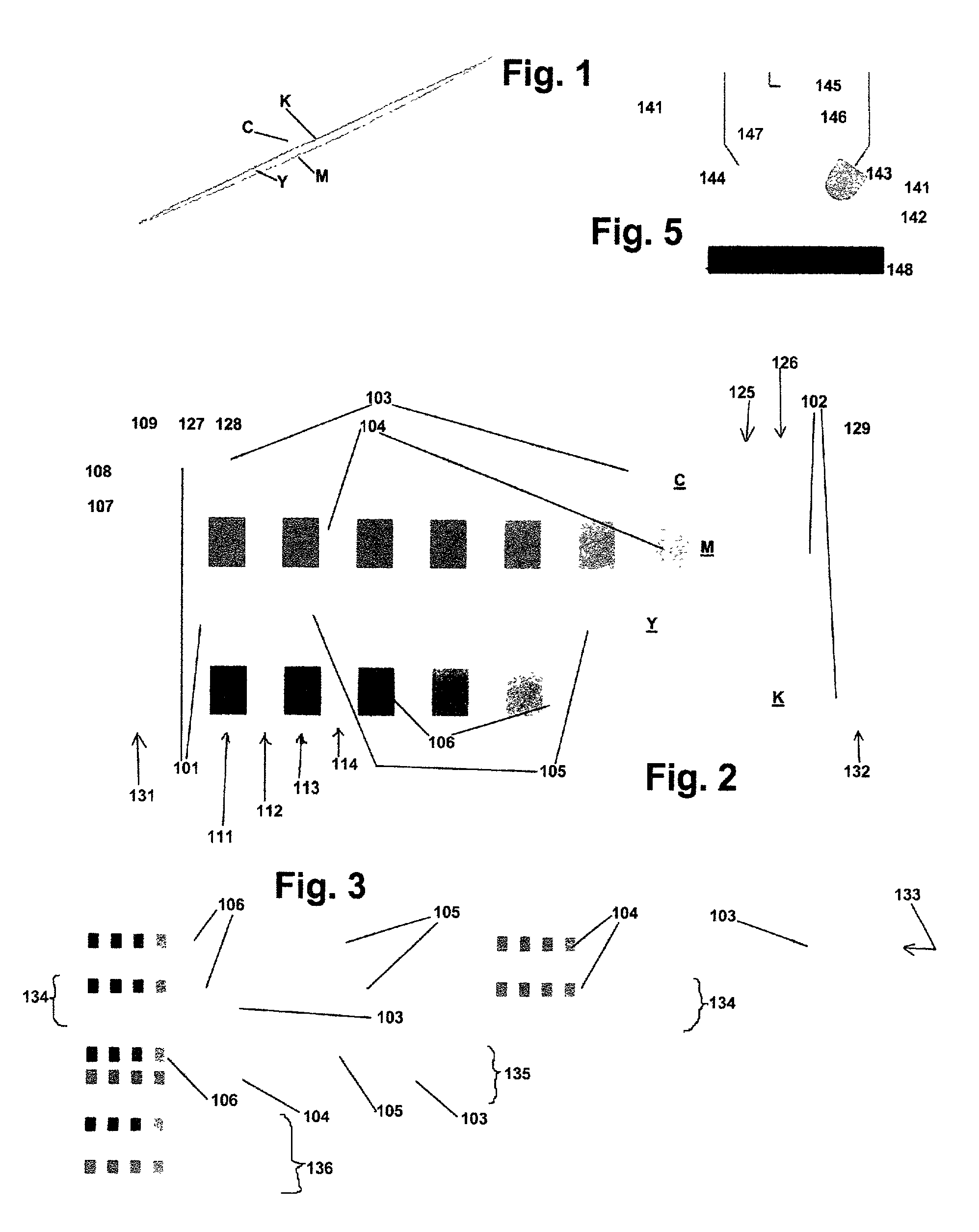
[0044]When the applying step includes adjusting the sensor response to substantially each color patch in substantially all the patterns—as described above—then preferably the printing step includes automatically arranging some of the patch sequences for each test pattern to fit an available size of the medium. For this purpose the sequences may be arranged either side-by-side or one above the other on the printing medium. Here the disposition of each sequence between two unprinted areas is maintained—and also the steps of exposing the two adjoining unprinted areas, and interpreting the two sensor unprinted-adjoining-area responses, are maintained—notwithstanding the automatic arranging. In this way the method is made robust to use of different printing-medium sizes.
[0057]In particular, even if the measurement signals are intrinsically unreliable due to either the light source or detector still warming up during the measurement, nevertheless the signals can be rendered fully reliable. This is achieved by the simple provision of reference area(s) and the interpreting means.
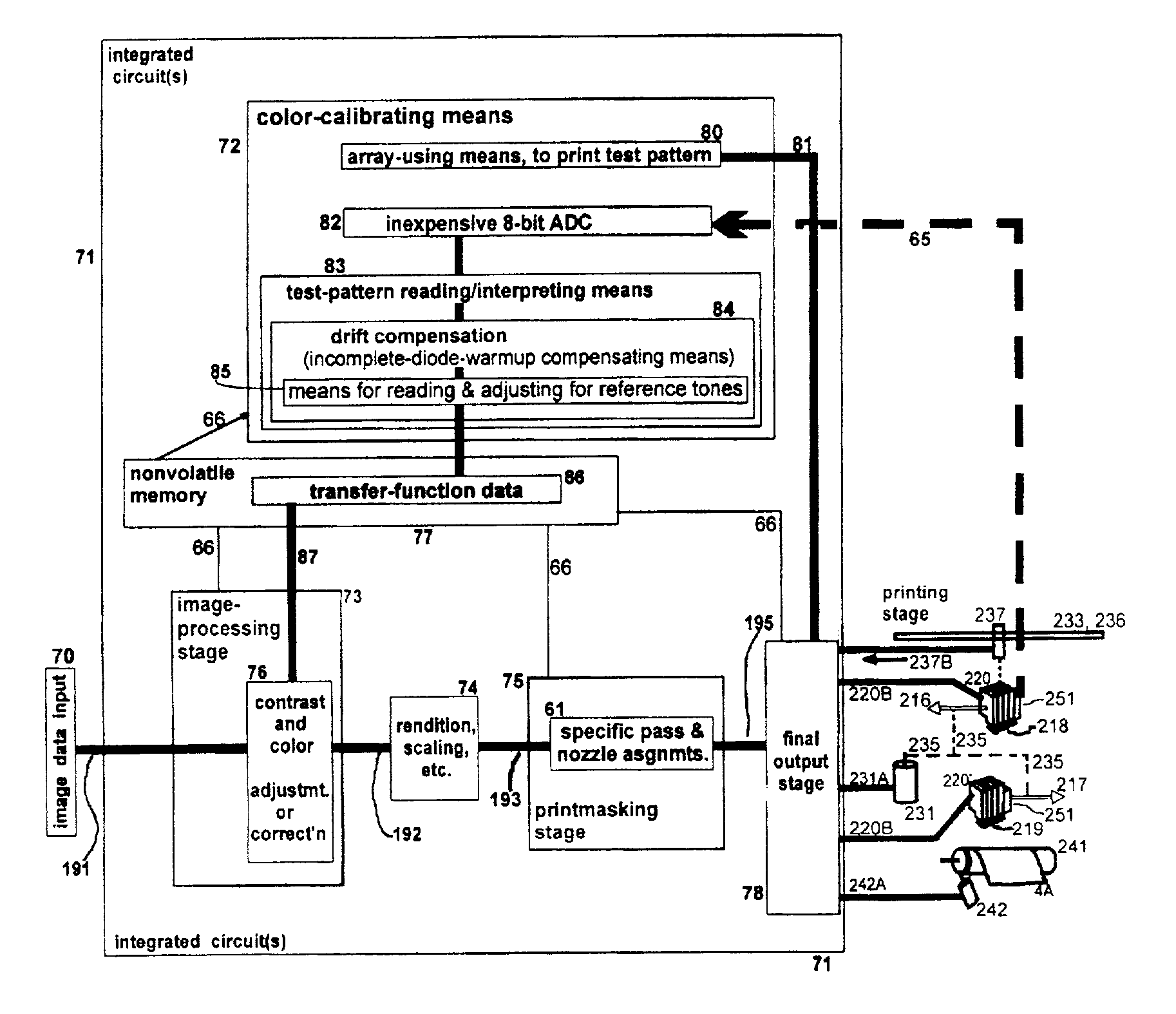
[0073]Thereby the apparatus accommodates the printhead tolerances and diode temperature dependence, and avoids the converter nonlinearities. In this way the invention itself resolves the several problems noted above.

Problems solved by technology

Manufacturing tolerances, often quite broad—in the interest of economy—in these and other printer parameters result in a deviation between the actual and the targeted color.
Range displacement most typically is more difficult to bring under control because it implicates the linearity and stability of every element—optical, electronic and mechanical—in the signal train.
The detector and its ADC nevertheless have the far greater challenge of responding not just at a single level but linearly over the full possible range of the optical signals from the test pattern.
The computer-printer field, however, is extraordinarily price-competitive—and a detector and ADC of such quality are costly.
Again, this approach mitigates, but does not eliminate, demands on the measurement elements.
Thus the sensor and ADC are forced into use in an unfavorable mode: the small differences are as small as always, but the “large number” (the d. c. level) is generally doubled.
Although this difficulty has been couched in terms of the LEDs currently favored, a similar unfavorable relationship would arise even for a single, spectrally continuous source.
As noted above, this relationship has been found acceptable if an adequately linear ADC is in use, but this condition requires a relatively costly ADC.
Such cost can be made acceptable in a high-end system, but in a more economical printer is very undesirable.
(e) Sensor proximity—Surprisingly, even the above-mentioned concurrently developed high-end system, notwithstanding its relatively higher cost, has been found to exhibit a peculiar kind of instability in the calibration process.
Nevertheless, despite amply adequate sensor stability per se, accurate calibration has been found elusive in this system.
Nevertheless these minuscule displacements are more than sufficient to cause major fluctuations in light reflected from the printing medium to the detector.
Particularly awkward is a distinct nonlinearity of these displacements, and of the resulting optical fluctuations, with position along the scan axis.
(f) Conclusion—As this discussion shows, limitations of linearity, stability and price in economical systems—and also of mechanical tolerances in even a relatively expensive system—continue to impede achievement of uniformly excellent color calibration and therefore inkjet printing.

Method used


Image

  • Compensating for drift and sensor proximity in a scanning sensor, in color calibrating incremental printers
  • Compensating for drift and sensor proximity in a scanning sensor, in color calibrating incremental printers
  • Compensating for drift and sensor proximity in a scanning sensor, in color calibrating incremental printers

Examples


Embodiment Construction

1. Stability vs. Linearity vs. Cost

[0118]As noted in the earlier “Background” section of this document, the problem left unsolved for relatively inexpensive printing systems was how to more economically provide signal linearity and discrimination that are adequate for a good color calibration. It is also observed there that an inexpensive ADC could be sufficient if a lower standard of linearity could be tolerated, and in turn that such a system would accomplish the goal if only the overall light level could be made half as high.

[0119]Halving the illumination level, however, seemed to fly in the face of a requirement for full spectral illumination, with ample warmup time. Illumination over the full spectrum cannot be achieved by running just one LED.

[0120]On the other hand, operating only one source at a time—i. e. alternating two LEDs, with adequate warmup in each ramp-measurement cycle—would take a prohibitively long time for all the lamp-warmup intervals. The invention, however, a...


PUM


Abstract

To compensate for color-calibration sensor drift, a measurement of bare-print-medium tonal value is taken in immediate time juxtaposition to each color test pattern; measured bare-medium tone is then used to correct color-patch readings. A line sensor or the like, on the scanning printhead carriage, is used for the reading. Preferably two such readings are taken, one at each end of each test pattern; ideally separate scans of the bare medium are taken without any test-pattern patch to develop longterm and short-term drift profiles, for refining the corrections. To compensate for calibration error due to runout in the carriage track—particularly for wide-bed printers—sensor response to bare medium is used to represent variations in carriage-to-medium spacing along the track; these variations are corrected in later sensor use.

Description

RELATED PATENT DOCUMENTS[0001]Related documents include other, coowned U.S. utility-patent documents hereby incorporated by reference in their entirety into this document. One is in the names of Francesc Subirada et al. and filed, very generally concurrently with the present document, and later assigned application Ser. No. 09 / 919,207. Another is in the names of Thomas Baker et al. and is application Ser. No. 09 / 183,819, later issued as U.S. Pat. No. 6,832,824. Yet another is in the name of Antoni Gil Miquel, Ser. No. 09 / 642,417.FIELD OF THE INVENTION[0002]This invention relates generally to inexpensive machines and procedures for incremental printing of text or graphics on printing media such as paper, transparency stock, or other glossy media; and more particularly to details of operating a scanning sensor for color calibration in such economical machines and procedures.BACKGROUND OF THE INVENTION[0003](a) Color calibrationColor reproduction is affected by printer variables, whic...

Claims


Application Information

Patent Timeline
IPC IPC(8): B41J1/00G06F15/00H04N1/46H04N1/407H04N1/60
CPCH04N1/6033H04N1/4078
Inventor SOLER, PAUVINAS, ROGERRODRIGUEZ, FRANCISCO JAVIERSUBIRADA, FRANCESC
Owner HEWLETT PACKARD DEV CO LP
Learn More