
Transportable security portal for screening potential terrorists

a security portal and transportable technology, applied in the field of transportable security portals, can solve the problems of enormous security risk of microscopic bio-hazard, no known security systems provide rapid screening of potential terrorists, and can not be easily damaged,

Inactive Publication Date: 2006-04-04
STOMSKI GERALD D
View PDF16 Cites 45 Cited by
  • Summary
  • Abstract
  • Description
  • Claims
  • Application Information

AI Technical Summary

Benefits of technology

[0013]It is a more specific purpose to provide a transportable security portal for screening potential terrorists that may be readily transported to areas of a short-term, high security demand in order to screen potential terrorists.
[0014]It is an additional object to provide a transportable security portal that can also contain any hazardous materials transported by potential terrorists upon detection of the hazardous materials to prohibit contamination of the area of high security demand by the detected hazardous materials.

Problems solved by technology

While these provide for isolating a potential terrorist during a screening search, because of the limited mobility and structural limitations of such known security systems, the systems are of virtually no or limited value in screening individuals at areas of a high security demand for a limited period of time, such as an area receiving a visit by a head of state, etc.
Additionally, no known security systems also provide for rapid screening of potential terrorists as well as containment of hazardous materials a terrorist may seek to unleash in a “suicide attack”.
For example, the well-known anthrax attacks on the U.S. Senate Office buildings of the Fall and Winter of 2001–2002 presented an enormous security risk of a microscopic bio-hazard.
If such a lethal contaminant were to be carried into a high security area with a temporary high population density and unleashed by a suicide bomber, the results could very well be catastrophic.

Method used


Image

  • Transportable security portal for screening potential terrorists
  • Transportable security portal for screening potential terrorists
  • Transportable security portal for screening potential terrorists

Examples


Embodiment Construction

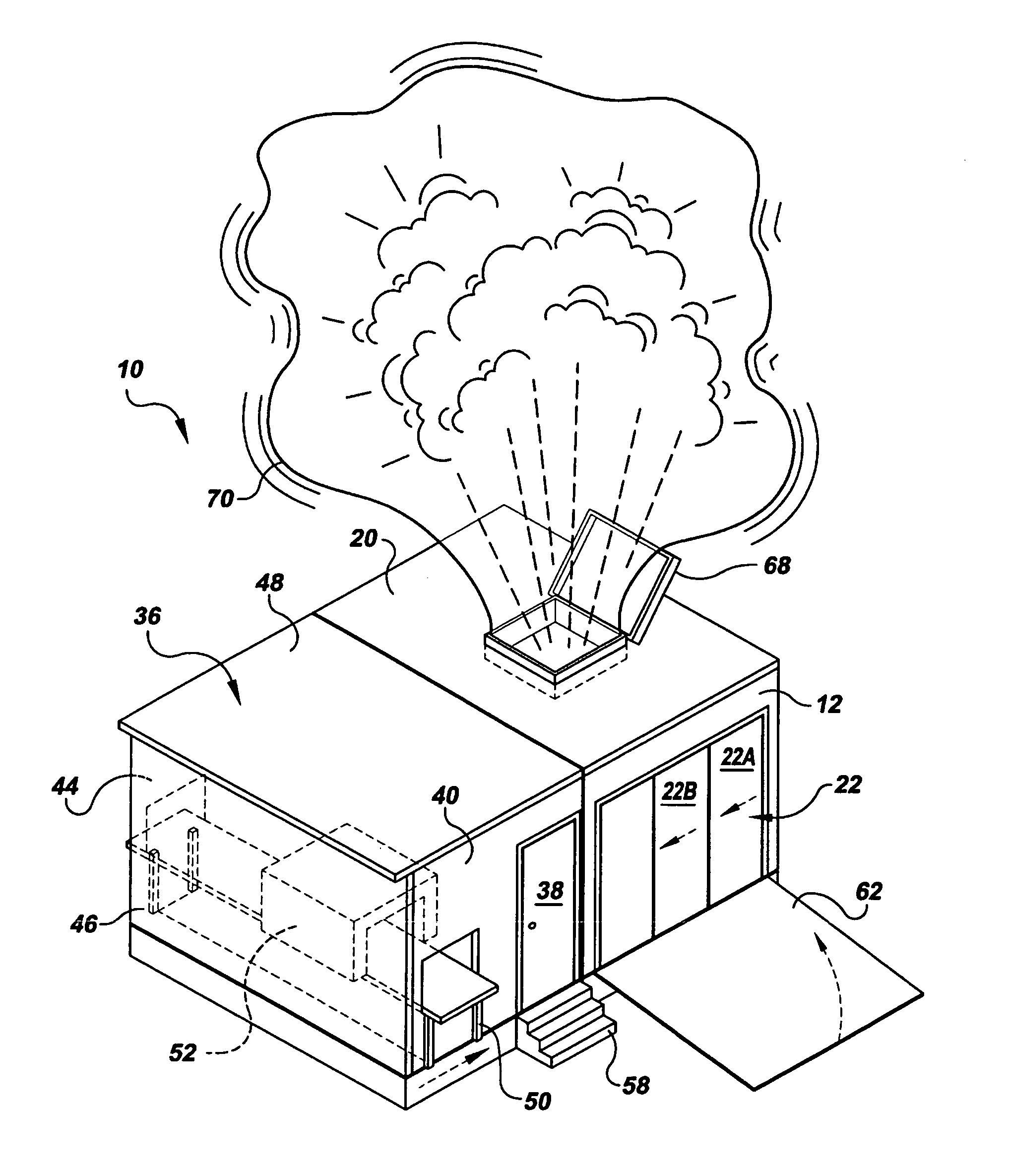
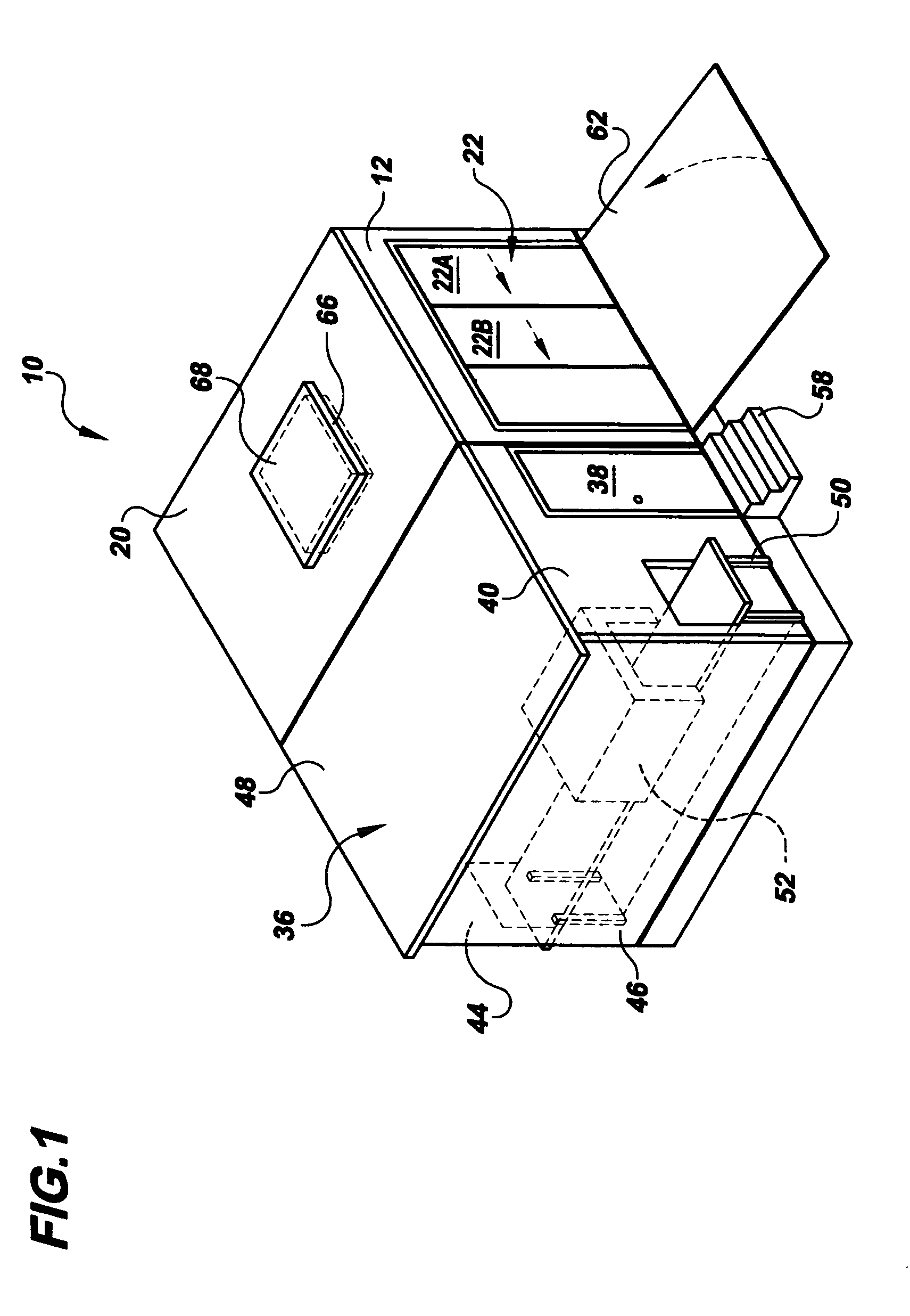
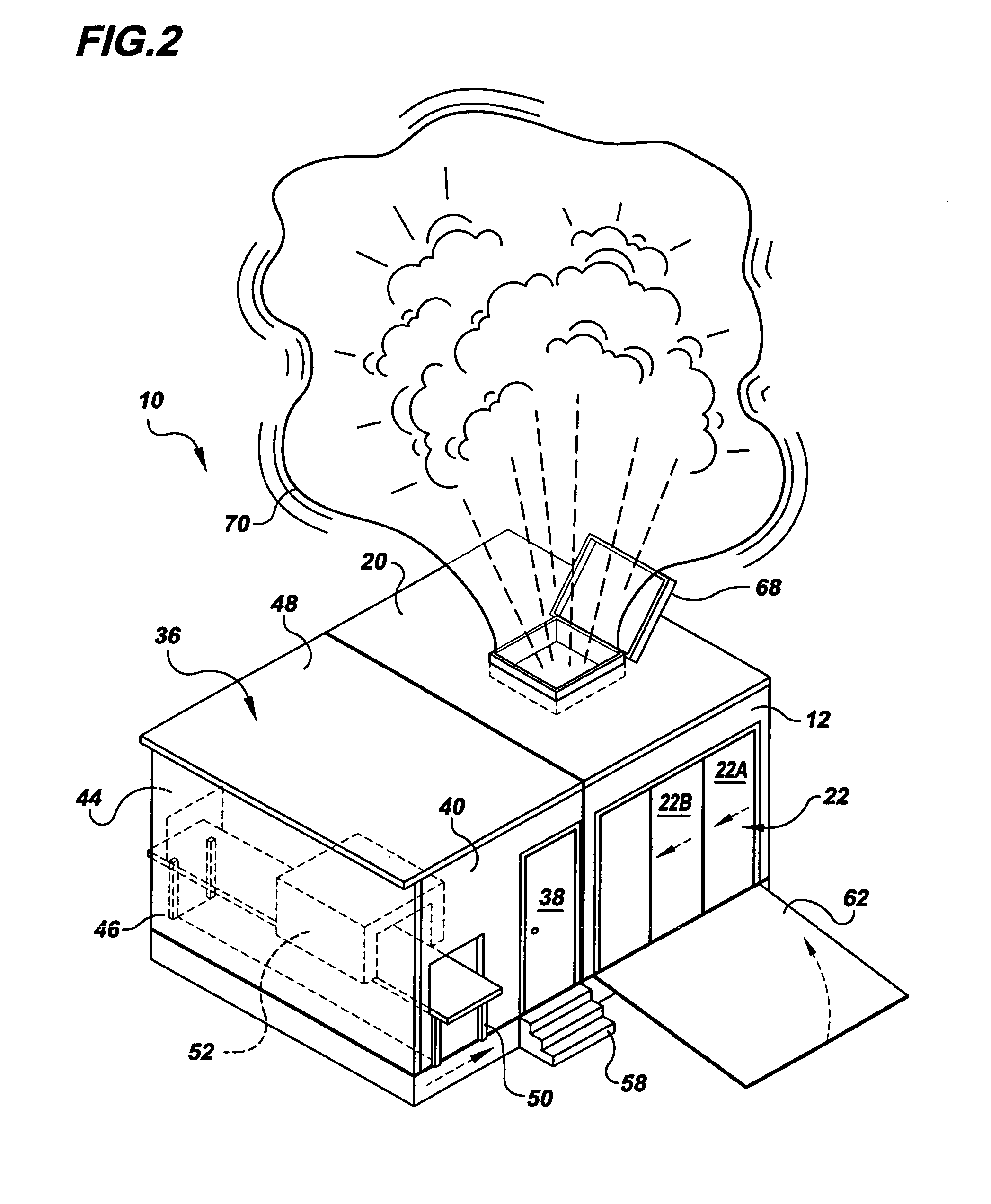
[0020]Referring to the drawings in detail, a transportable security portal for screening potential terrorists is shown and generally designated by the reference numeral 10. The security portal 10 includes a portal entry wall 12, a first side portal wall 14 and an opposed second side portal wall 16 (shown in FIG. 3), a portal exit wall 18, and a roof 20. The portal entry wall 12 includes a portal entry door 22, that may be a sliding door including a first sliding panel 22A, and a second sliding panel 22B, and having a manual or automated opening mechanism, as disclosed in the aforesaid, incorporated U.S. Pat. No. 6,484,650, or may be any kind of door known in the art to be capable of being bullet-resistant and locked for security purposes recited herein. The portal exit wall 18 includes a portal exit door 24, that, like the front portal door 22, may be a sliding door including a first sliding panel 24A, and a second sliding panel 24B, and that may also have a manual or automated open...


PUM


Abstract

The security portal (10) is dimensioned to be readily mounted and transported on a trailer (54) alone as a single security portal (10) or with a plurality of security portals to provide screening for a short term, high security event. The portal (10) includes bullet-resistant, bomb-blast proof and at least partially transparent walls (12, 14, 16, 18) and doors (22, 24, 26). Monitors (32, 34) are secured to the portal (10) for monitoring an individual within an interior (30) of the portal (10) for detecting weapons, bio-hazards, chemical toxins, illegal drugs, contraband, or other hazardous materials. The security portal also includes a security monitoring station (36) adjacent the security access door (26) and a bomb-blast enclosure (66) having a flap (68) and bomb-blast containment balloon (70) for containing hazardous materials in the event of a bomb-blast within the portal (10).

Description

TECHNICAL FIELD[0001]The present invention relates to apparatus for screening individuals passing from non-secure areas into secure areas, and in particular relates to a transportable, small security portal that may be readily moved as a single portal or along with a plurality of identical security portals to a high security event, such as a visit by a well-known government dignitary, or major sporting events, such as the Olympics, Super Bowl, etc.BACKGROUND ART[0002]It is well known that, in the wake of the terrorist attacks of Sep. 11, 2001 in New York City, Washington, DC and Pennsylvania, heightened security concerns have given rise to new solutions to the many problems associated with screening individuals to prevent terrorist activities. The present inventor has provided one such solution that is disclosed in U.S. Pat. No. 6,484,650 that issued on Nov. 26, 2002 to Stomski, which Patent is incorporated herein by reference.[0003]That patent shows a security system for queues or ...

Claims


Application Information

Patent Timeline
Patent Type & Authority Patents(United States)
IPC IPC(8): G08B21/00E04H9/06G08B19/00
CPCE04H9/06G01V5/0008
Inventor STOMSKI, GERALD D.
Owner STOMSKI GERALD D
Learn More