
Single particle electrochemical sensors and methods of utilization

Active Publication Date: 2006-04-04
SANDIA NAT LAB
View PDF9 Cites 11 Cited by
  • Summary
  • Abstract
  • Description
  • Claims
  • Application Information

AI Technical Summary

Benefits of technology

[0009]From the above summary it appears that the desirable properties for an improved sensor design are: 1) the ability to work at the statistical limit of sensitivity, 2) single-step operation, 3)

Problems solved by technology

The problem is that the method has no way of confirming if a given single particle was actually the target analyte, or something to which the Abs bound through non-specific binding (NSB) interactions.
There are also limitations in throughput for all of these methods, in that detecting a single particle in a given volume requires somehow processing at least that much volume (preferably several times the volume to allow for a given statistical level of surety).
Again, although it is in principle possible to address these difficulties through scaling (multiple independent channels operating simultaneously), this can only be done at the cost of greater instrumental complexity.
For example, in flow cytometry, once the fluorescently-labeled particle passes through the laser-based fluorescence detection portion of the cytometer, the fluors are generally destroyed (through photo-bleaching), so that particle cannot be re-assayed without stripping off the (rather tightly bound) Ab labels and re-labeling.
Fluorescence measurement of a natively fluorescent particle (i.e., molecules) may result directly in photodestruction of the particle.
Direct electrochemical detection also generally results in chemical alteration of the analyte.
It is not feasible to construct a million element electrode array and monitor current with a million potentiostats in a small device.

Method used


Image

  • Single particle electrochemical sensors and methods of utilization
  • Single particle electrochemical sensors and methods of utilization
  • Single particle electrochemical sensors and methods of utilization

Examples


Embodiment Construction

[0031]The present invention, described hereinafter, involves devices for affinity-based electrochemical detection of particles with single-particle sensitively. The particles can be cells, bacteria, viruses, aggregates, immunocomplexes or molecules. The devices described may be employed as sensors or assays for a single type of particle, or for a range of particle types, and may be configured in arrays having both these attributes. Also described are methods for using these devices to achieve extremely high sensitivity and high specificity detection of specific particles. These devices and methods would generally be used as sensors for particles dissolved or suspended in a solution.

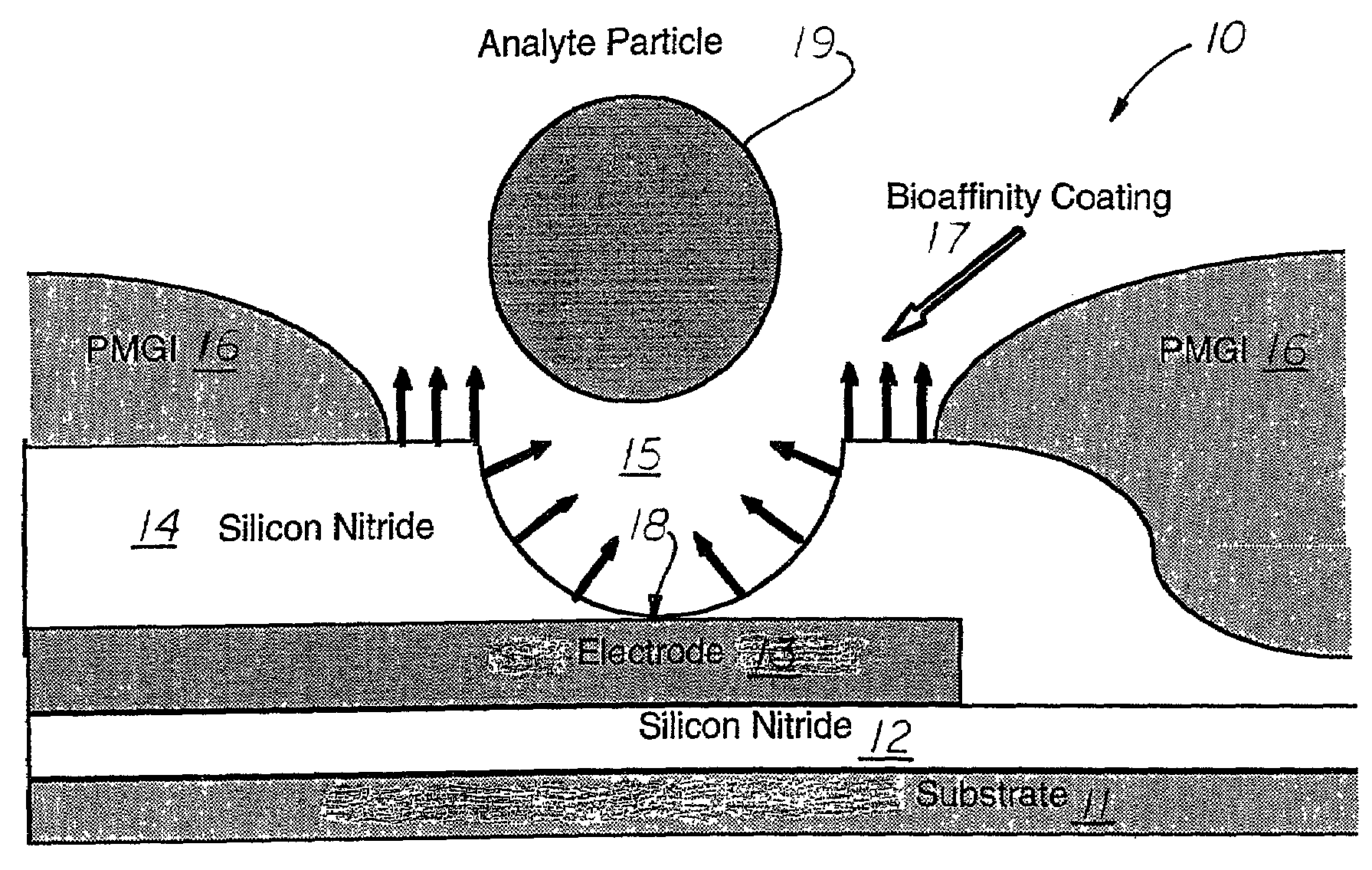
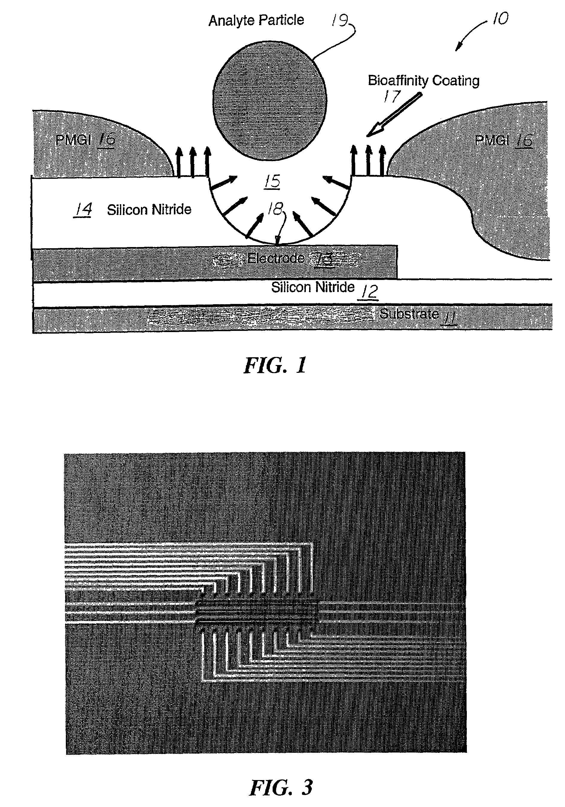
[0032]These devices and methods employ a surface-attached specific affinity components (e.g., antibodies, combinational peptides, glycolipids) to selectively capture a particle on elements of an array of single particle sensors. Such as array might contain a very large number of elements, or consist of ev...


PUM

PropertyMeasurementUnit
Thicknessaaaaaaaaaa
Affinityaaaaaaaaaa
aaaaaaaaaa

Abstract

The present invention discloses an electrochemical device for detecting single particles, and methods for using such a device to achieve high sensitivity for detecting particles such as bacteria, viruses, aggregates, immuno-complexes, molecules, or ionic species. The device provides for affinity-based electrochemical detection of particles with single-particle sensitivity. The disclosed device and methods are based on microelectrodes with surface-attached, affinity ligands (e.g., antibodies, combinatorial peptides, glycolipids) that bind selectively to some target particle species. The electrodes electrolyze chemical species present in the particle-containing solution, and particle interaction with a sensor element modulates its electrolytic activity. The devices may be used individually, employed as sensors, used in arrays for a single specific type of particle or for a range of particle types, or configured into arrays of sensors having both these attributes.

Description

[0001]The United States Government has rights in this invention pursuant to Contract No. DE-AC04-94AL85000 between the United States Department of Energy and the Sandia Corporation for the operation of the Sandia National Laboratories.BACKGROUND OF THE INVENTION[0002]The present invention relates to particle detection devices, particularly to devices for single-particle detection and to methods for using the devices to achieve extremely high sensitivity detection of specific particles, and more particularly to devices for affinity-based electrochemical detection of particles with single-particle sensitivity, and wherein a single device or an array of devices employing surface-attached specific affinity components may be used to selectively capture particles.[0003]Various approaches to detection of particles in a solution have been developed over the years. Molecular Recognition Materials (MRMs) capable of selective binding to a particle are used in a wide range of assays and sensors...

Claims


Application Information

Patent Timeline
IPC IPC(8): G01N15/06G01N27/22G01N33/543
CPCG01N33/5438G01N27/22
Inventor SCHOENIGER, JOSEPHFLOUNDERS, ALBERT W.HUGHES, ROBERT C.RICCO, ANTONIO J.WALLY, KARLKRAVITZ, STANLEY H.JANEK, RICHARD P.
Owner SANDIA NAT LAB
Learn More