Pipe washing method and pipe washing apparatus

Inactive Publication Date: 2006-03-28
HONDA TOSHIMI
View PDF10 Cites 8 Cited by
  • Summary
  • Abstract
  • Description
  • Claims
  • Application Information

AI Technical Summary

Benefits of technology

[0011]To solve the above problems, a pipe washing method of the present invention is characterized by comprising the step of intermittently or continuously driving carbon dioxide gas into a pipe to wash the interior thereof by the foaming action of the carbon dioxide gas dissolved in the water in the pipe. Here, the dissolved carbon dioxide gas can be easily vaporized by flowing water in the pipe, and the interior of the pipe can be washed by reliably removing water stain, scale, rust, and the like deposited on the inner wall of the pipe by the action of the vaporized carbon dioxide gas. Further, at this time, when a crack arises in a part of the pipe, the driven carbon dioxide gas spouts out from the crack portion. Thus, the cracked portion of the pipe can be easily found by spouting noise, thereby water leakage can be investigated simultaneously with the washing of the pipe. Further, since carbon dioxide gas, which is used also in drinking water, is used, the pipe washing method exhibits excellent characteristics in the aspect of hygiene.
[0012]A pipe washing apparatus of the present invention is characterized by comprising gas cylinders filled with carbon dioxide gas, a dispersing device for intermittently or continuously spouting the carbon dioxide gas supplied from the gas cylinders, and a connection hose for causing the dispersing device to communicate with a pipe to be washed. With this arrangement, a large-scale facility such as a compressor, a large water tank, and the like are not necessary, thereby an equipment investment cost and an operation process can be reduced.
[0013]In the pipe washing apparatus of the present invention, it is preferable that a pressure valve for discharging gas and water in the pipe when the pressure in the pipe reaches at least a predetermined level be interposed between the dispersing device and the connection hose. With this arrangement, the breakage of the pipe caused by the pressure of the charged carbon dioxide gas can be prevented before it arises.

Problems solved by technology

Further, at this time, when a crack arises in a part of the pipe, the driven carbon dioxide gas spouts out from the crack portion.

Method used


Image

  • Pipe washing method and pipe washing apparatus
  • Pipe washing method and pipe washing apparatus
  • Pipe washing method and pipe washing apparatus

Examples


Embodiment Construction

[0033]Specific embodiments of the present invention will be described below in detail.

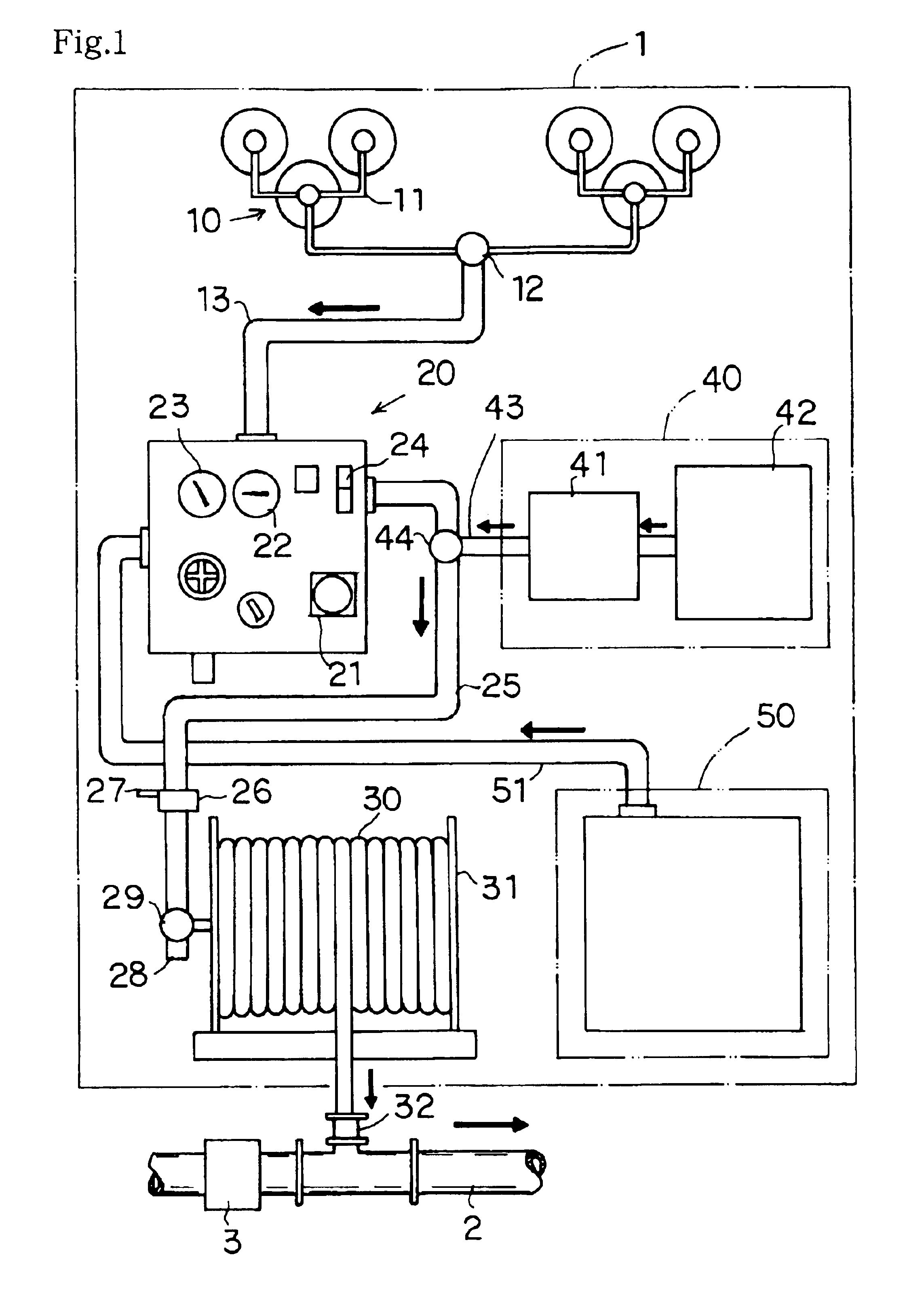
[0034]First, embodiments of a pipe washing method and a pipe washing apparatus of the present invention will be described. FIG. 1 is an overall schematic view showing an example of the pipe washing apparatus of the present invention.

[0035]The illustrated pipe washing apparatus 1 includes gas cylinders 10 filled with compressed carbon dioxide gas a, a dispersing device 20 capable of continuously or intermittently spouting the carbon dioxide gas a supplied from the gas cylinders 10, and a connection hose 30 for causing the dispersing device 20 to communicate with a pipe 2 to be washed.

[0036]A plurality of the gas cylinders 10 are coupled with each other through gas pipes 11 and connected to a gas hose 13 through an open / close valve 12. Further, an opposite end of the gas hose 13 is coupled with the dispersing device 20, and the carbon dioxide gas a in the gas cylinders 10 is supplied into the dispers...


PUM

PropertyMeasurementUnit
Pressureaaaaaaaaaa
Stress optical coefficientaaaaaaaaaa
Displacementaaaaaaaaaa

Abstract

A micro device in which a functional element can be moved between an operating position and a waiting position by the displacement of support means coupled to a substrate. The micro device has a cantilever structure in which one end of support means is made a fixed one fixed to the substrate and the other end to which an active element is provided is made a free end. A spring portion is provided to at least part of the support means, and thus the active element can be greatly displaced by a small stress.

Description

[0001]This application is the national phase under 35 U.S.C. § 371 of PCT International Application No. PCT / JP02 / 08682 which has an International filing date of Oct. 2, 2001, which designated the United States of America.TECHNICAL FIELD[0002]The present invention relates to a pipe washing method and a pipe washing apparatus, and more particularly, to a pipe washing method and a pipe washing apparatus capable of effectively washing the interiors of pipes (water supply pipes and the like) of buildings, factories, and the like as well as capable of investigating water leakage in the pipes. Further, the present invention relates also to a well pipe washing method and a well pipe washing apparatus capable of effectively washing the interiors of well pipes for pumping up underground water in a short time.BACKGROUND ART[0003]Usual buildings and complex housing have pipes (water supply pipes and the like) installed therein for supplying drinking water and water for other applications. Used ...

Claims


Application Information

Patent Timeline
IPC IPC(8): B08B9/02E21B37/00B08B9/032B08B9/04B81B3/00B81C1/00G02B6/35G02B26/08
CPCB08B9/0323G02B26/0833B08B9/0433B08B9/0325
Inventor HONDA, TOSHIMI
Owner HONDA TOSHIMI
Why Eureka
Try Eureka