
Apparatus and method for controlling the temperature of an electronic device

Inactive Publication Date: 2006-03-28
DELTA DESIGN
View PDF23 Cites 31 Cited by
  • Summary
  • Abstract
  • Description
  • Claims
  • Application Information

AI Technical Summary

Benefits of technology

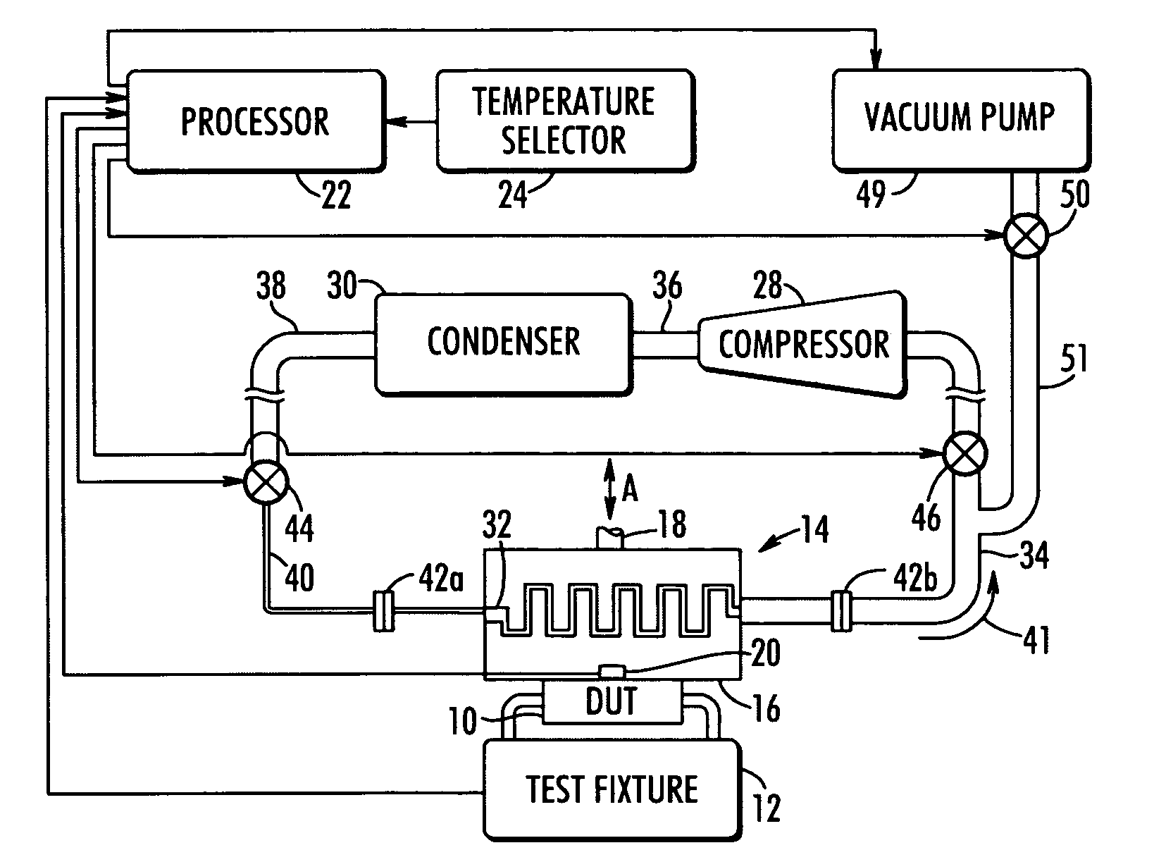
[0014]In another aspect, the present invention provides an apparatus for controlling the temperature of an electronic device. The apparatus comprises a refrigeration system including a compressor and a condenser. The refrigeration system is operative to circulate a refrigerant fluid through a fluid flow loop such that the refrigerant fluid will cha

Problems solved by technology

This causes a loss of refrigerant fluid from the refrigeration system, which must be replaced (or “recharged”) before the refrigeration system will be operational again.
Moreover, testing equipment may be limited in the types of devices that can be tested.
This can lead to increased costs for both testing equipment and maintenance.
Where the refrigeration system is used in an application other than testing, the maintenance of the electronic equipment may lead removal of components of the refrigeration system, which could result in increased costs and complexity.

Method used


Image

  • Apparatus and method for controlling the temperature of an electronic device
  • Apparatus and method for controlling the temperature of an electronic device
  • Apparatus and method for controlling the temperature of an electronic device

Examples


Embodiment Construction

[0034]It is to be understood by one of ordinary skill in the art that the present discussion is a description of exemplary embodiments only and is not intended as limiting the broader aspects of the present invention, which broader aspects are embodied in the exemplary constructions.

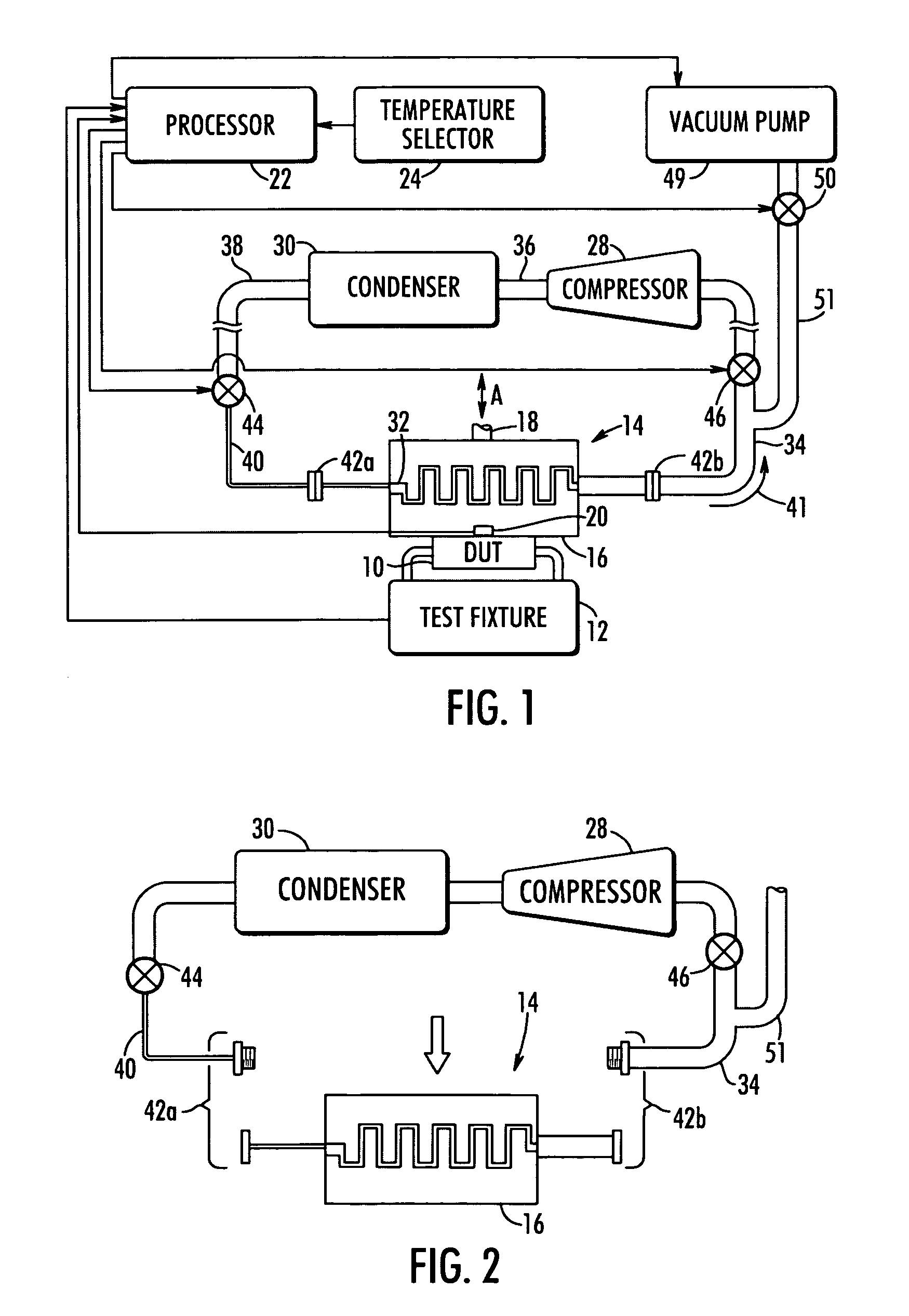
[0035]FIG. 1 illustrates an apparatus for controlling the temperature of an electronic device 10 under test (“DUT”). Although the invention will be described in conjunction with a DUT, one of ordinary skill in the art should appreciate that the invention could be used to control the temperature of other electronic devices. Moreover, the present invention could be applied to mechanical devices. For example, the temperature of a motor could controlled using the present invention. Further, the present invention could be applied to other components in a refrigeration system, such as filters or dryers and compressors, even though it will be discussed in conjunction with a thermal head below. Further, it shoul...


PUM


Abstract

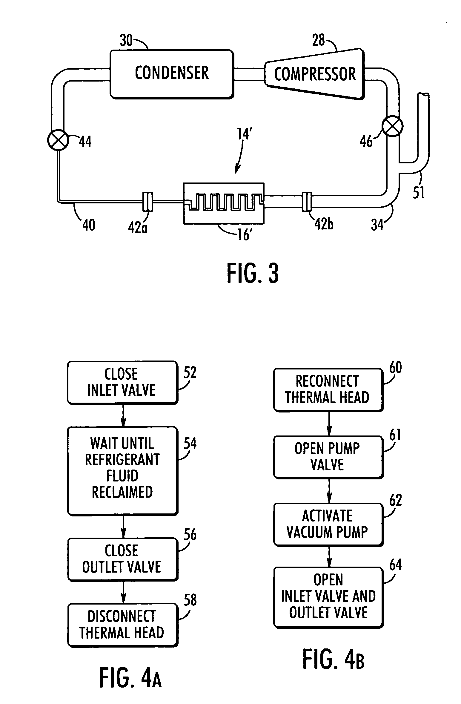
An apparatus for controlling the temperature of an electronic device under test includes a thermal head. The thermal head defines a flow channel for passage of a refrigerant fluid so as to cause transfer of thermal energy between the electronic device and the thermal head. A refrigeration system is connected in fluid communication with the flow channel of the thermal head to supply refrigerant fluid thereto. An inlet valve and outlet valve are provided to facilitate disconnection of the thermal head from the refrigeration system. The valves are sequentially closed with the refrigeration system continuing to operate during the interim period so as to reclaim the refrigerant fluid. Accordingly, thermal head may be disconnected from refrigeration system and removed.

Description

PRIORITY CLAIM[0001]This application claims priority to Provisional Application Ser. No. 60 / 455,774, filed on Mar. 19, 2003, which is hereby incorporated by reference.BACKGROUND OF THE INVENTION[0002]The present invention generally relates to temperature control systems for maintaining the temperature of an electronic device at a predetermined temperature such as while the device is being tested.[0003]Testing equipment has been utilized in the electronics industry to test the operation of an electronic device under test (DUT) such as an integrated circuit. Often, the testing equipment will include a thermal head having a temperature controlled surface which is brought into thermal engagement with a top surface of the DUT. The thermal head functions to maintain a predetermined temperature during the testing operation.[0004]With some such testing equipment, the thermal head is configured as an evaporator in a refrigeration system including a compressor and condenser. Refrigerant fluid...

Claims


Application Information

Patent Timeline
IPC IPC(8): F25B1/00F25B9/00F25B43/04F25B45/00F25D19/00F25D23/12G01R31/02G01R31/26G01R31/28G01R31/302H01LH05K7/20
CPCG01R31/2891G01R31/2855F25B45/00F25B2345/002
Inventor WAYBURN, LEWIS S.SPEARING, IAN G.GAGE, DEREK E.
Owner DELTA DESIGN
Learn More