Image-formation optical system and optical apparatus
a technology of optical system and optical apparatus, applied in the field of image-formation optical system, can solve the problems of difficult mechanical adjustment, difficult to overcome manufacturing discrepancies in surface precision or decentering, and often sensitive off-axial optical systems using such reflective surfaces, and achieve the effect of small performance deterioration and sufficient compactness
- Summary
- Abstract
- Description
- Claims
- Application Information
AI Technical Summary
Benefits of technology
Problems solved by technology
Method used
Image
Examples
embodiment 1
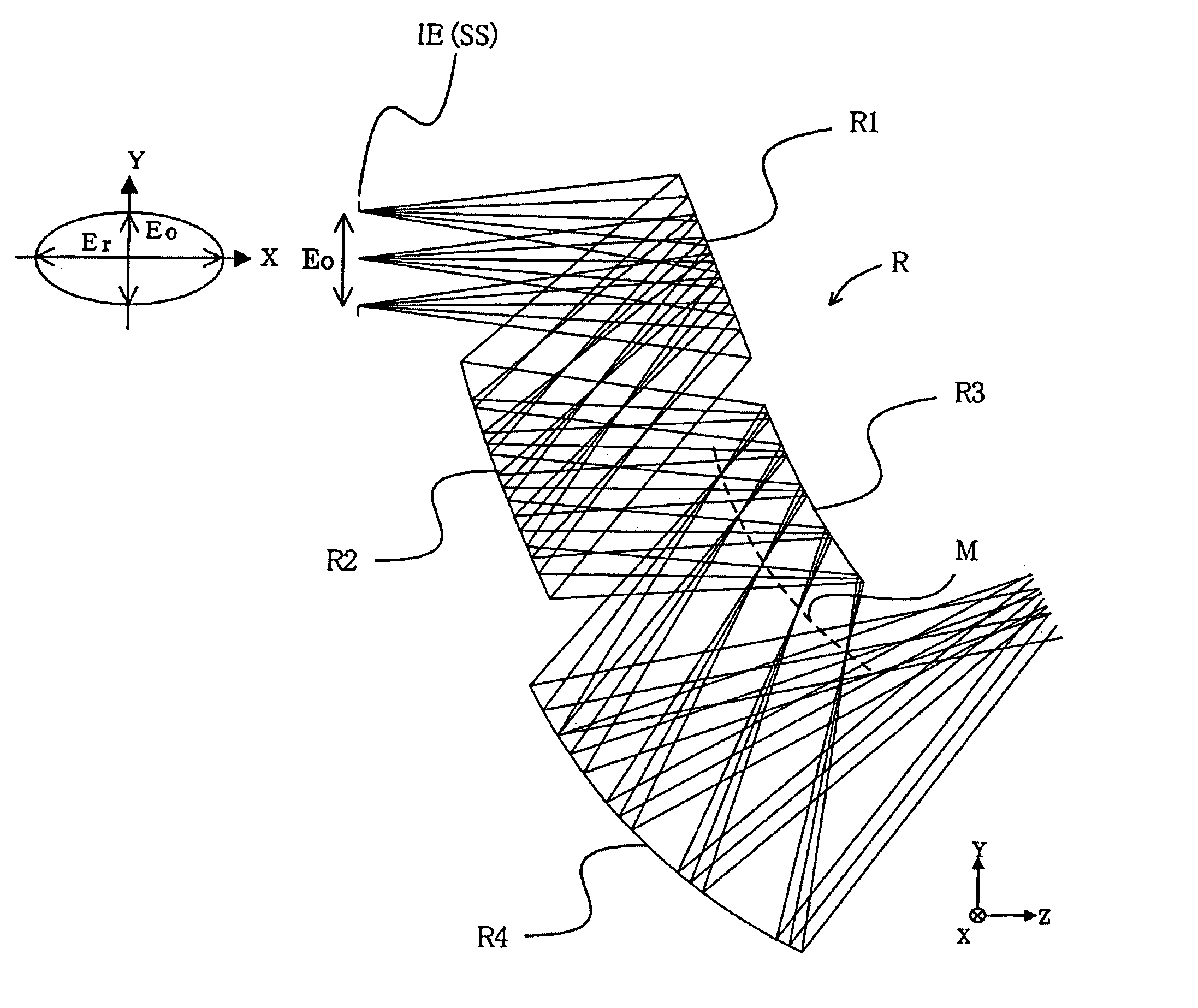
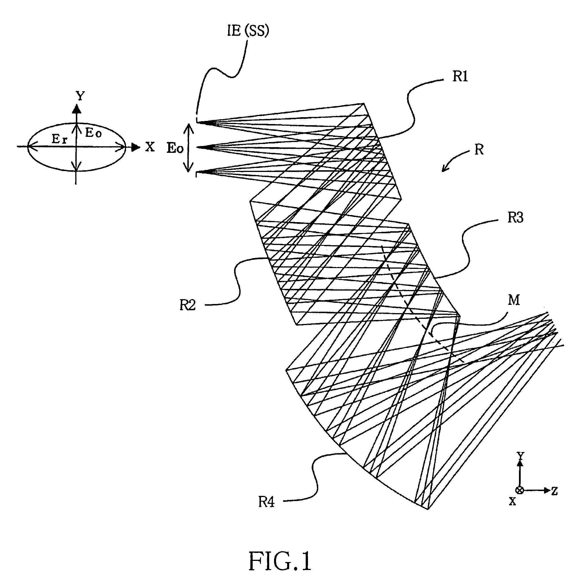
[0072]FIG. 1 is a cross-sectional view illustrating an image-formation optical system according to Embodiment 1 of the present invention. The image-formation optical system in FIG. 1 is a projection optical system, and is used, for example, in an image projection apparatus, such as shown in FIG. 10.
[0073]In FIG. 10, LO denotes an illumination system, which includes a lamp 1 that is a white light source, a reflection mirror 2, and a color separating element (not shown in FIG. 10) which separates the white light emitted from the lamp 1 into the three color light components of red, green and blue.
[0074]LV denotes a transmission-type liquid crystal display panel serving as an image-generating unit. This liquid crystal display panel LV is connected to a driver circuit 10, and the driver circuit 10 is connected to an image information supplying apparatus 20, such as a personal computer, a DVD player, a video recorder (VCR), a television, a digital video recorder, a digital still camera, o...
numerical example 1
[0112]Entrance pupil diameters of off-axial reflective optical unit: Eo: 13.50 mm; Er: 27.00 mm
[0113]
surf.YiZiDiθxb, i1 (SS)0.000.0053.000.00aperture stop2 (R1)0.0053.0045.0023.00refl. surf.3 (R2)−32.3721.7445.00−23.00refl. surf.4 (R3)−32.3766.7453.7930.00refl. surf.5 (R4)−78.9539.852370.00−16.00refl. surf.61033.702132.4325.40image surf.
aspherical surface shapes:[0114]surface 2 (R1)[0115]C02: −6.6929E-04 C03: 1.9942E-05 C04: 3.5238E-07[0116]C05: −4.0546E-09 C06: −3.6492E-10 C20: −1.1272E-03[0117]C21: 2.2639E-05 C22: 3.6858E-07 C23: −1.4852E-09[0118]C24: −3.6534E-10 C40: 8.3629E-08 C41: 2.2826E-09[0119]C42: −2.6622E-11 C60: 9.3704E-12[0120]surface 3 (R2)[0121]C02: 2.4430E-03 C03: 2.9178E-05 C04: −9.4344E-09[0122]C05: −7.4058E-09 C06: −9.0694E-11 C20: 2.1859E-03[0123]C21: 3.9969E-05 C22: −7.4362E-08 C23: −9.4285E-09[0124]C24: −1.3730E-10 C40: 4.1582E-08 C41: −6.6813E-10[0125]C42: 3.8725E-11 C60: 4.6869E-12[0126]surface 4 (R3)[0127]C02: 5.0704E-03 C03: −2.3209E-05 C04: −2.5925E-06[0128...
embodiment 2
[0141]FIG. 4 is a cross-sectional view illustrating the structure of the reflective optical unit of a projection optical system (image-formation optical system) according to Embodiment 2 of the present invention. The projection optical system of this embodiment is used for an image projection apparatus, like the projection optical system of FIG. 1, which is explained in Embodiment 1. Moreover, the reflective optical unit of the present embodiment is made of four reflective surfaces R1 to R4, like the reflective optical unit of Embodiment 1. However, the entrance pupil diameters of the reflective optical unit of the present embodiment satisfy the following equation:
Er=4Eo
[0142]Table 1 shows the size of the off-axial reference axis angles of the reflective optical unit in FIG. 4, and Table 2 shows the optical path length L (equivalent value in air) from the first reflective surface R1 to the final reflective surface R4 normalized by the entrance pupil diameter Er and the number S of r...
PUM
 Abstract
Description
Claims
Application Information
 - R&D
- Intellectual Property
- Life Sciences
- Materials
- Tech Scout
- Unparalleled Data Quality
- Higher Quality Content
- 60% Fewer Hallucinations
Browse by: Latest US Patents, China's latest patents, Technical Efficacy Thesaurus, Application Domain, Technology Topic, Popular Technical Reports.
© 2025 PatSnap. All rights reserved.Legal|Privacy policy|Modern Slavery Act Transparency Statement|Sitemap|About US| Contact US: help@patsnap.com


