
Singulator

a technology of singulator and cylinder, applied in the direction of conveyer parts, transportation and packaging, etc., can solve the problems of increasing the dimensions of the conveyer in that direction, not being free from limitations and/or operational problems, and not being able to ensur

Active Publication Date: 2017-01-03
MECHANICA SISTEMI
View PDF50 Cites 8 Cited by
  • Summary
  • Abstract
  • Description
  • Claims
  • Application Information

AI Technical Summary

Benefits of technology

The aim of this patent is to create a compact and easy-to- manage and control singulator that can handle a high number of articles per unit of time and is highly reliable. This will be achieved by reducing the number of motors, electronics, and mechanical parts in motion and ensuring good singulation performance.

Problems solved by technology

The singulators briefly described above, while admirably fulfilling the tasks they are designed for, are not free from limitations and / or operational problems.
For example, the singulators described above are not able to assure the correct singulation of articles in the event that two or more of said articles are superimposed on one another.
Furthermore, the need to be able to recirculate products that have not been singulated requires the presence of two further recirculating belts positioned at the sides of the machine, which obviously increases the dimensions thereof in that direction.
What is described above generally implies the need to have large volumes / dimensions in order to install the singulators in question, resulting in increases in the costs of both constructing the device and managing the machine itself.
On the other hand, as the device has a multiplicity of conveyor belts that are independently movable, it is much more compact, but at the same time, extremely complex in terms of the construction and management of the operation thereof.
Furthermore, each of the conveyor belts is equipped with a respective drive and a respective motor, which clearly increase the costs of construction and maintenance, while at the same time reducing the reliability of the singulator (considering the high number of electrical and mechanical parts that make it up).

Method used


Image

  • Singulator
  • Singulator
  • Singulator

Examples


Embodiment Construction

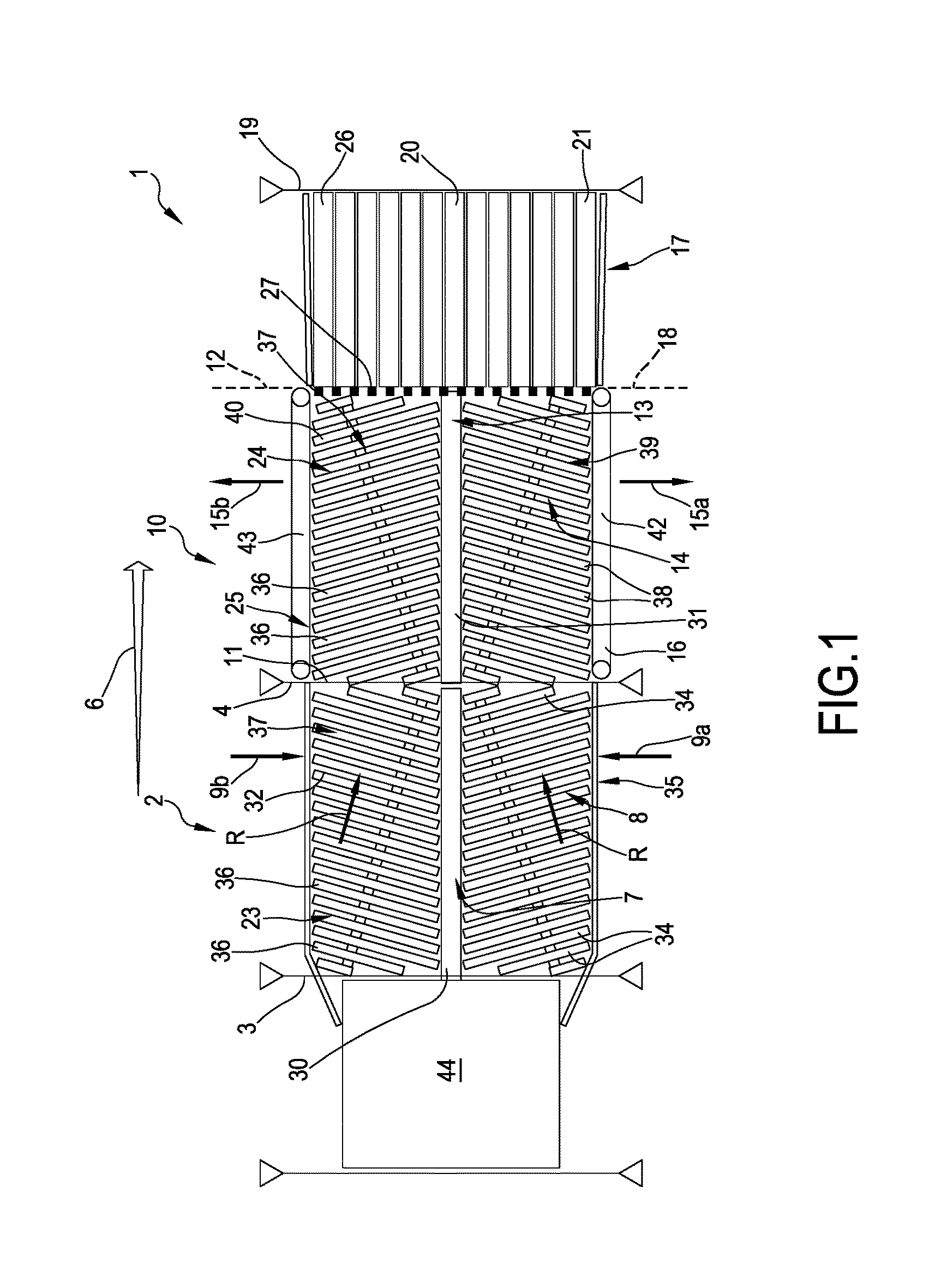
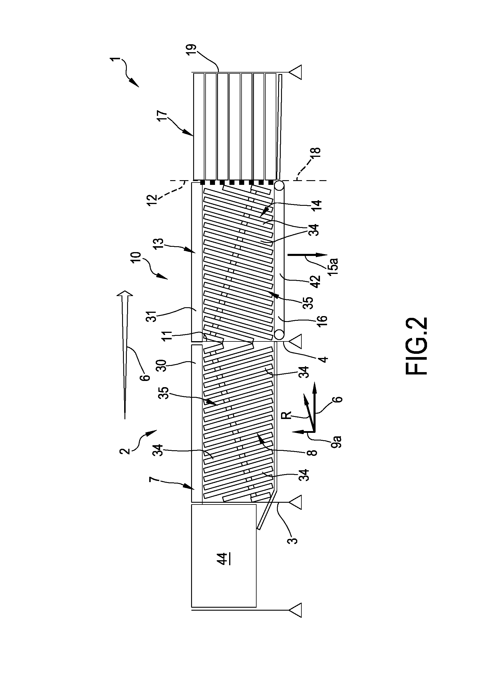
[0105]With reference to the aforesaid figures, 1 denotes in its entirety a singulator as described below.

[0106]In particular, and as previously mentioned, the singulator that is the subject matter of the following description is particularly intended for the singulation of loosely arranged items 5.

[0107]In particular, the articles 5, which may have undergone further manipulation if necessary before reaching the inlet of the singulator (e.g. unstacking operations for supplying them to the inlet in a two-dimensional configuration) are brought to the inlet of the singulator by a suitable conveyor belt (or equivalent system) for infeeding them to the main modules of the singulator.

[0108]In particular, the products initially reach an inlet station 3 of a converger module 2.

[0109]The converger module 2 extends longitudinally along a main direction 6 of advancement of the articles between the above-mentioned inlet station 3 and an outlet station 4.

[0110]In general, the loose articles 5 ent...


PUM


Abstract

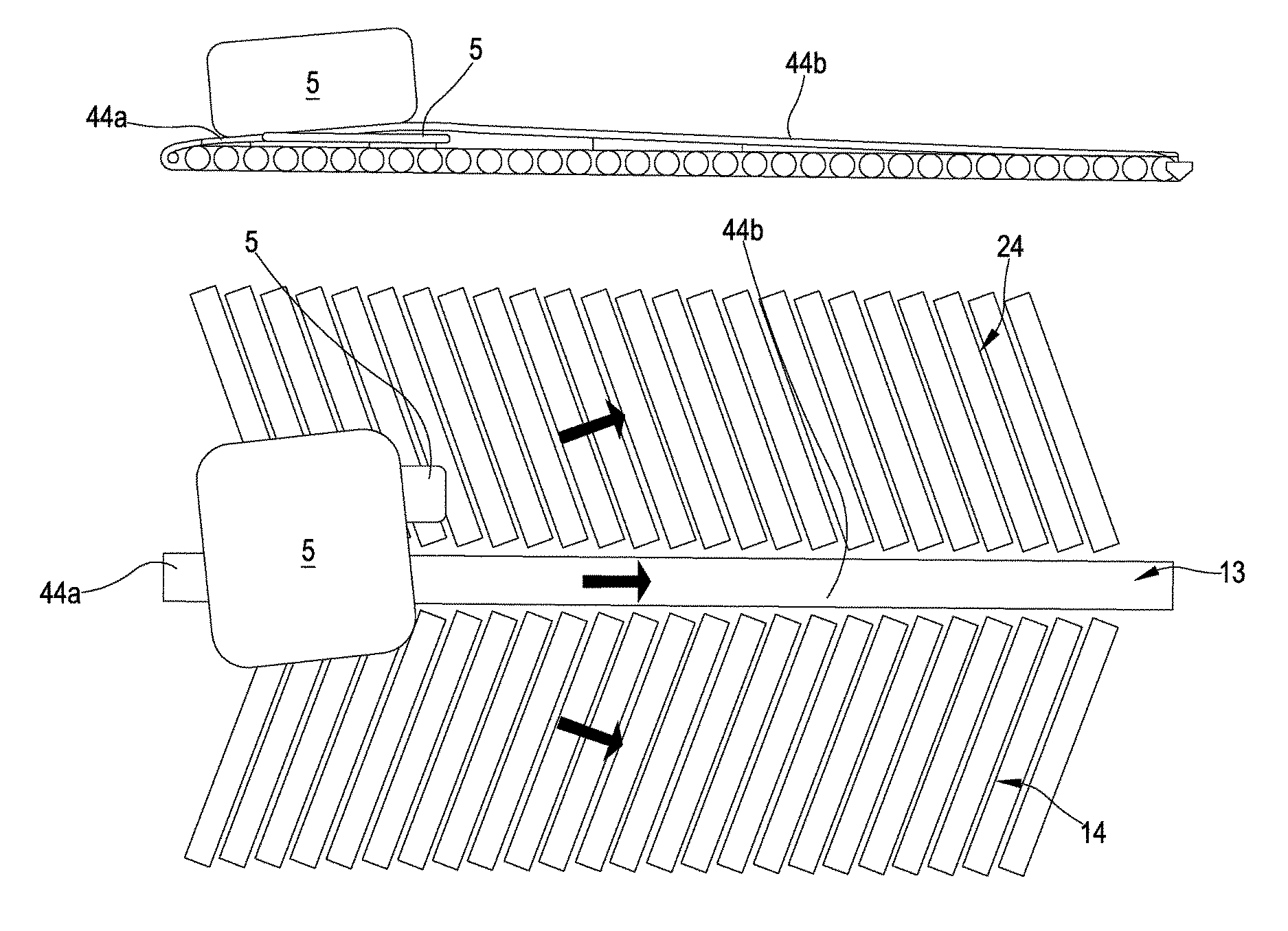
A singulator has been realized which comprises a diverger module extending between an inlet station and an outlet station; the diverger module is configured to receive articles at the inlet station and convey them towards the outlet station along a main advancement direction. The diverger module has: a first zone extending from the inlet station to the outlet station and configured to impart to the articles resting thereon an advancement motion along the main advancement direction, a second zone flanking the first zone along the advancement direction and extending between the inlet station and the outlet station. The second zone is configured to impart to the articles resting thereon an advancement motion along the main direction and a lateral movement away from the first zone. The first zone of the diverger module projects, at least for a length, away from a prevalent average plane of extension of the second zone in the direction of the articles to be supported so as to define an ascent zone of the diverger module.

Description

[0001]This application is a national stage application of International Application No. PCT / IB2014 / 059390, filed internationally on Mar. 3, 2014, which claims priority to Italian Application No. MI2013A000318, filed Mar. 4, 2013, the entire contents of each of which is incorporated by reference herein.[0002]The present invention relates to a singulator, intended in particular to receive a plurality of incoming loose articles and to output the aforementioned plurality of articles, suitably singulated (in one or more lines), i.e. arranged consecutively along predetermined advancement lines.TECHNOLOGICAL BACKGROUND[0003]As is known, many commercial and industrial activities require a fixed number of articles that are generally fed randomly and are loosely ordered and then automatically sorted so that they can thereafter be handled more easily in an automatic or semi-automatic way.[0004]The machines designed for this operation are known as “singulators”.[0005]The areas of use of singula...

Claims


Application Information

Patent Timeline
Patent Type & Authority Patents(United States)
IPC IPC(8): B65G47/30B65G47/26B65G47/68B65G47/22
CPCB65G47/682B65G47/22B65G47/268B65G47/30
Inventor CRISTOFORETTI, GIORGIO
Owner MECHANICA SISTEMI
Learn More