
Device for improving visibility in vehicles

Inactive Publication Date: 2006-03-21
SIEBEL SYST INC +1
View PDF15 Cites 76 Cited by
  • Summary
  • Abstract
  • Description
  • Claims
  • Application Information

AI Technical Summary

Benefits of technology

[0010]An object of the present invention is to produce an angle-dependent radiation pattern of the laser light in a simple manner.
[0011]The present invention provides a device for improving visibility in a vehicle, especially in darkness, bad weather and fog, including one or more laser headlights radiating laser light of a wavelength outside the visible spectrum into a predetermined solid angle area ahead of the vehicle, a camera which is sensitive outside the visible spectrum and used for taking images of current traffic scenes, as well as an optical display system in the vehicle for reproducing the captured images in the visible spectrum. At least two different types of laser headlights are provided which each illuminate different parts of the solid angle area to be observed.
[0012]Because the laser light is emitted by two or more different types of laser headlights which each illuminate different parts of the solid angle area to be observed, it is possible for the type of the laser light source, the optical power, the optics and, possibly, the wavelength of the respective laser headlights to be optimally adapted the specific purpose of illumination, for example, for a “road headlight” and a “person or pedestrian headlight”. By suitable selection of the parts of the solid angle area to be observed which are illuminated by the different types of laser headlights and of the overlapping regions thereof, it is possible for the overall radiation pattern to be optimized in a simple manner.

Problems solved by technology

Bad visibility at night is a tiring and dangerous situation which is feared by many drivers.
At night, in particular, the following difficulties occur:With low beams in case of oncoming traffic, the range of vision is low and misjudged by many drivers.
This results in late detection of unlighted obstacles, pedestrians, bicyclists without light and of animals and consequently results in accidents.The driver is dazzled by the headlights of oncoming vehicles and their reflexes, in particular, when the roadway is wet; the driver drives into a black hole for a short period of time.
This is a danger especially to night-blind and aged drivers because of their low visual performance.In rain, fog and blowing snow, the visibility conditions can even be markedly worse.
However, high demands are placed on the mechanism required for tilting the mirror, which are difficult to meet in the case of a vehicle.

Method used


Image

  • Device for improving visibility in vehicles
  • Device for improving visibility in vehicles

Examples


Embodiment Construction

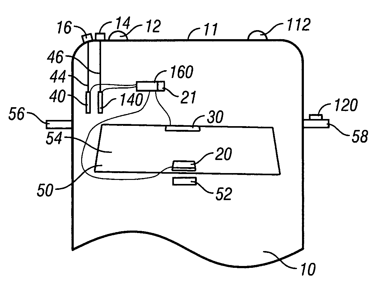
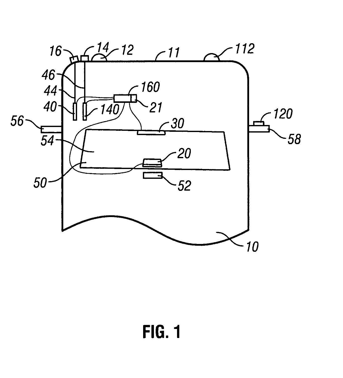
[0034]FIG. 1 shows a vehicle 10 having conventional headlights 12, 112 and laser headlights 14, 16 radiating laser light of a wavelength outside the visible spectrum into a predetermined solid angle area ahead of the vehicle. A camera 20 is sensitive outside the visible spectrum and is used for taking images of current traffic scenes. An optical display system 30 in the vehicle reproduces the captured images in the visible spectrum. Laser headlights 14, 16 each illuminate different parts of the solid angle area to be observed.

[0035]Lasers 40, 140 generating the laser light are arranged in a location remote from a front 11 of the vehicle 10 and are connected to the laser headlights 14, 16 via light guides 44, 46.

[0036]The camera 20 is attached behind the windshield 50 of the vehicle 10 at the level of the inside rearview mirror 52.

[0037]An infrared-reflecting film 54 on the windshield 50 of the vehicle is left open in the region of the field of view of the camera 20.

[0038]Camera 20 p...


PUM


Abstract

The present invention relates to a device for improving visibility in a vehicle, especially in darkness, bad weather and fog, including one or more laser headlights radiating laser light of a wavelength outside the visible spectrum into a predetermined solid angle area ahead of the vehicle, a camera which is sensitive outside the visible spectrum and used for taking images of current traffic scenes, as well as an optical display system in the vehicle for reproducing the captured images in the visible spectrum. According to the present invention, provision is made for at least two different types of laser headlights which each illuminate different parts of the solid angle area to be observed to produce an angle-dependent radiation pattern of the laser light in a simple manner.

Description

[0001]Priority to German Patent Application No. 101 31840.5-51, filed Jun. 30, 2001 and incorporated by reference herein, is claimed.BACKGROUND INFORMATION[0002]The present invention relates to a device for improving visibility in a vehicle.[0003]Bad visibility at night is a tiring and dangerous situation which is feared by many drivers. As a consequence of bad visibility, the accident frequency is markedly higher at night than while traveling during the day and in good visibility. At night, in particular, the following difficulties occur:[0004]With low beams in case of oncoming traffic, the range of vision is low and misjudged by many drivers. This results in late detection of unlighted obstacles, pedestrians, bicyclists without light and of animals and consequently results in accidents.[0005]The driver is dazzled by the headlights of oncoming vehicles and their reflexes, in particular, when the roadway is wet; the driver drives into a black hole for a short period of time. This is...

Claims


Application Information

Patent Timeline
IPC IPC(8): H04N7/18G01S17/931B60Q1/00G03B15/00B60Q1/02B60Q1/08B60R1/00B60R1/06B60R1/12B60R21/00G03B15/02G08G1/09G08G1/0962
CPCG01S17/936G01S2013/9367G01S2013/9323G01S17/931
Inventor HOLZ, MICHAELWEIDEL, EDGAR
Owner SIEBEL SYST INC
Learn More