Ignition device for igniting a foil cartridge in an explosion-operated power tool

a technology of igniting device and power tool, which is applied in the direction of manufacturing tools, nailing tools, etc., can solve the problems of undesirable presence of al/sub>2/sub>3 in the power tools of this type, mechanical rigidity of the insulator, and danger of the central electrode being thrown out of the insulator, etc., to achieve improved properties, increase the temperature stability of the foil cartridge, and improve the effect of pressure in the channel

Inactive Publication Date: 2006-03-21
HILTI AG
View PDF17 Cites 2 Cited by
  • Summary
  • Abstract
  • Description
  • Claims
  • Application Information

AI Technical Summary

Benefits of technology

[0010]By using an electrically conductive annular electrode, it became possible to form an electrical arc for igniting the foil cartridge directly between the pin-shaped electrode and the annular electrode. Thereby, there is no need to use foil cartridges with electrically conductive region, e.g., foil cartridges with aluminum foils. This results in clean burning as no Al2O3 is formed, and the power tool does not become soiled. With replacement of the conventional aluminum foils by plastic foils, the temperature stability of the foil cartridges increases, as plastic foils have better properties than the aluminum foil.
[0011]In order to penetrate through the electrically non-conductive plastic foil, the pressure in the channel is increased. This is achieved by making the channel very narrow so that an arc discharge fills the entire channel. The electrical arc resulting for the discharge has a temperature of about 3000° C. to 4000° C. The high temperature and the high dissociation of gases in the electrical arc provide for a build-up of a very high pressure which is capable to cut through the plastic foil of the cartridge or melt the plastic foil through. The recombination of the plasma, upon cooling down, frees a noticeable amount of energy used for ignition of the cartridge or the propellant.
[0012]The annular electrode is formed advantageously as a cover that pushes the insulator into a conical cavity in the support. This substantially increases the durability of the insulator. In addition, the annular electrode forms a bulge in the direction toward the cartridge support, i.e., it is convexly shaped at its side remote from the insulator. As a result, the cover foil of a cartridge is better pressed against the annular electrode when the cartridge is pressed by an axially displaceable sealing sleeve against the support. This reduces the danger of hot gases weakening the cover foil and penetrating in a space between the annular electrode and the cover foil. The annular electrode prevents direct contact of the powder loose particle with the insulator, better protecting the same.
[0013]According to a preferred embodiment of the present invention, the insulator is formed of a plastic material, which makes it more elastic and, therefore, less brittle than a ceramic insulator.
[0014]According to another preferred embodiment of the present invention, the annular electrode is screwed on the support, which permits to easily remove it, if needed, and replace it with a new one or a different one.
[0015]Advantageously, the spiral thread, which is used for screwing the annular electrode on the support, has an axial play. Thereby, the annular electrode is capable of following the springing of the insulator, keeping the hot gases away from the insulatory upon ignition of a cartridge. Mechanically, the annular electrode is formed similar to a disc spring. The elasticity of the annular electrode protects the insulator from mechanical overloading due to thermal expansion.

Problems solved by technology

However, the presence of Al2O3 in the power tools of this type is undesirable.
Moreover, the insulator is mechanically not sufficiently rigid, and there is a danger of the central electrode being thrown out from the insulator upon build-up of high pressure resulting from the ignition of the cartridge.
Furthermore, there exists a danger that hot, prestressed gases would flow through a gap between the electrode and the insulator and could cause further damage.

Method used


Image

  • Ignition device for igniting a foil cartridge in an explosion-operated power tool
  • Ignition device for igniting a foil cartridge in an explosion-operated power tool

Examples


Embodiment Construction

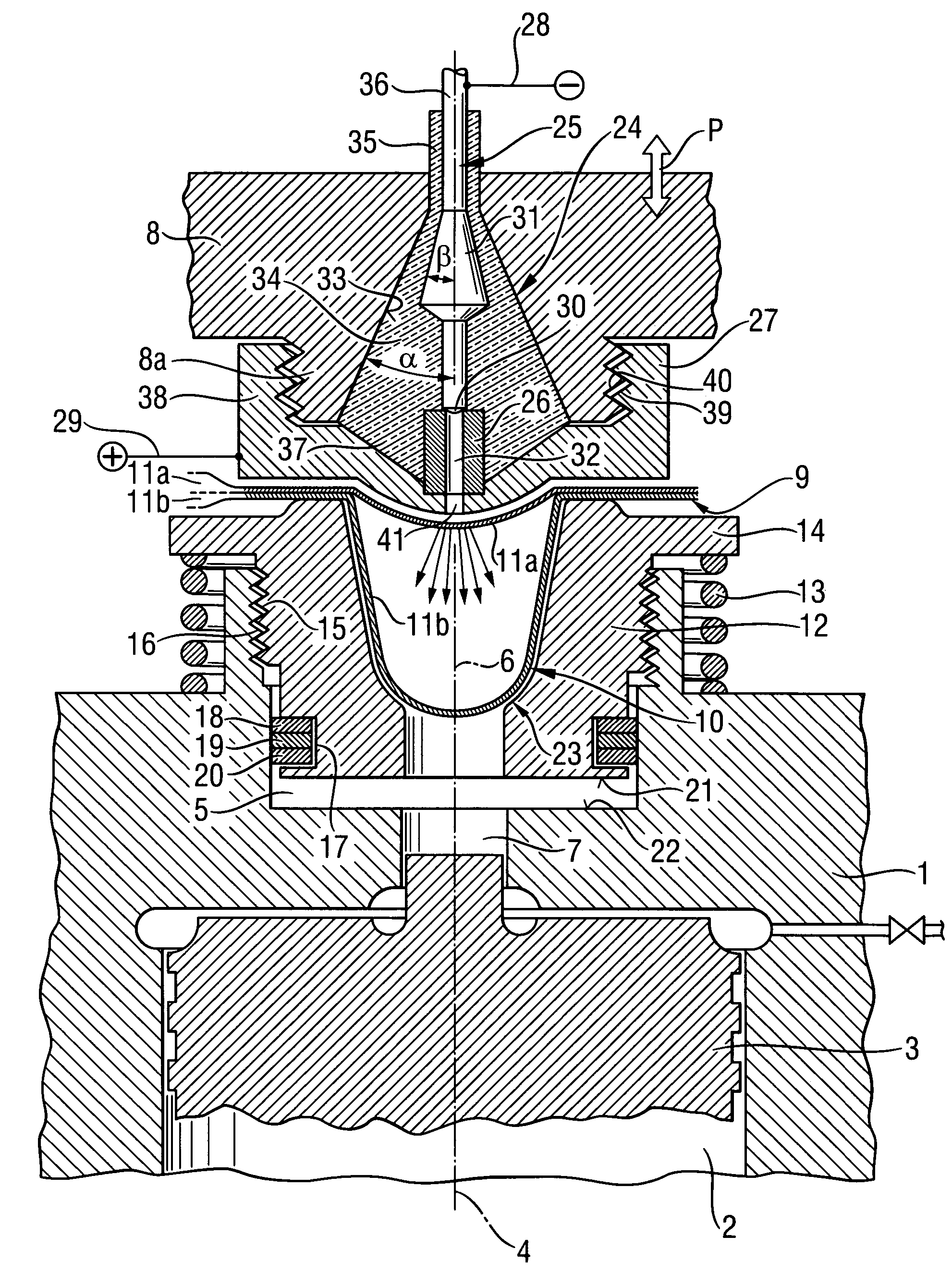
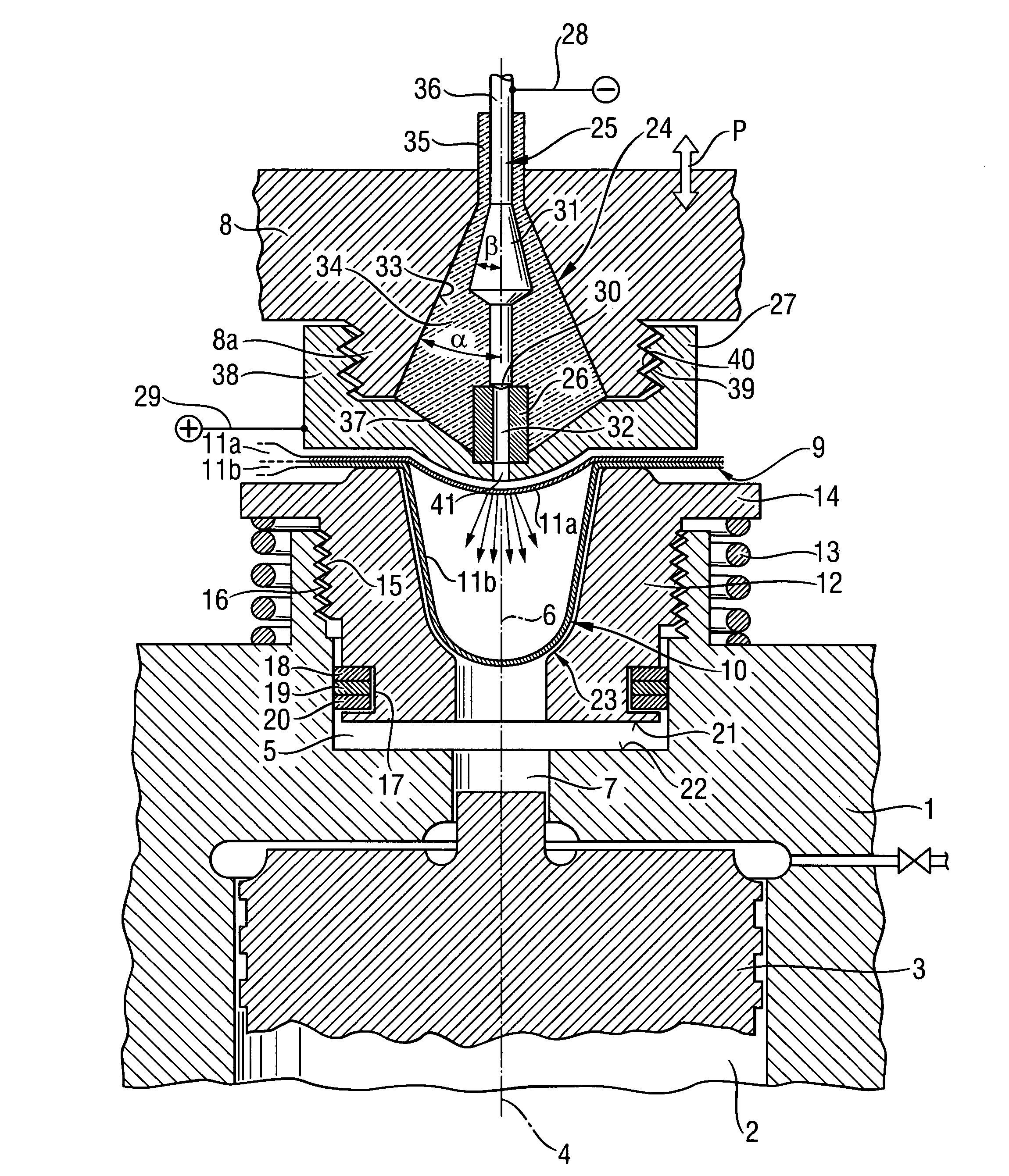
[0021]An ignition device according to the present invention for a foil cartridge for use in an explosion-operated power tool will be described by an example of its use in an explosive powder charge-operated power tool shown in the drawing. The power tool includes a housing 1 in which a cylindrical chamber 2 is formed. A drive piston 3 is arranged in the chamber 2 for displacement in the axial direction of the chamber 2. A central axis 4 of the chamber 2 extends in a longitudinal direction of the power tool. In the housing 1, there is formed a cylindrical cavity 5 the axis 6 of which coincides with the central axis 4 of the piston chamber 2. A connection channel 7, coaxial with respect to the central axis 4 of the piston chamber 2 and the axis 6 of the cylindrical cavity 5, connects the bottom region of the cavity 5 with the piston chamber 2.

[0022]Alternatively, the central axis 4 of the piston chamber 2 and the axis 6 of the cavity 5 can extend at an angle to each other, e.g., at a ...


PUM


Abstract

An ignition device for igniting a foil cartridge (10) in an explosion-operated power tool includes an electrical insulator (24) arranged in the support (8), a pin-shaped electrode (25) located in the electrical insulator and having a tip (30) that communicates with surrounding environment via a channel (32) formed in the electrical insulator (24) and extending in a longitudinal direction of the pin-shaped electrode (25) and an electrically conducting annular electrode (27) supported on the support (8) in a region of the channel (32) and tightly surrounding the insulator (24), leaving the channel (32) free.

Description

BACKGROUND OF THE INVENTION[0001]1. Field of the Invention[0002]The present invention relates to an ignition device for igniting a foil cartridge in a power tool and, in particular, in a setting tool for driving in fastening elements such as nails, bolts and the like.[0003]2. Description of the Prior Art[0004]German Publication DE-199 05 549 A1 discloses an ignition device for igniting foil cartridges in an explosive powder charge-operated setting tool for driving in fastening elements. The ignition device includes a support, an electrical insulator arranged in the support, a pin-shaped electrode located in the electrical insulator and having a tip that communicates with surrounding environment via a channel formed in the electrical insulator and extending in a longitudinal direction of the pin-shaped electrode. The electrical insulator is pressed during a setting process against an electrically conducting foil that forms a bottom of a foil cartridge. The electrical arc, which is fo...

Claims


Application Information

Patent Timeline
Patent Type & Authority Patents(United States)
IPC IPC(8): B25C1/08B25C1/10B25C1/14
CPCB25C1/143B25C1/10
Inventor DITTRICH, TILOEHMIG, GERHARD
Owner HILTI AG
Why Eureka
Try Eureka