Eureka AIR delivers breakthrough ideas for toughest innovation challenges, trusted by R&D personnel around the world.

Thermoelectric vehicle tracking device

Inactive Publication Date: 2006-03-14
HI Z TECH
View PDF3 Cites 21 Cited by
  • Summary
  • Abstract
  • Description
  • Claims
  • Application Information

AI Technical Summary

Benefits of technology

[0007]The present invention provides a tracking device for tracking a vehicle in which a radio transmitter is powered by heat energy of the exhaust system of the engine propelling the vehicle. A thermoelectric module is attached to a hot portion of the exhaust system. Electrical power generated by the thermoelectric module is used to pow

Problems solved by technology

Workers in the thermoelectric industry have been attempting too improve performance of thermoelectric devices for the past 20–30 years with not much success.
Most of the efforts to date with superlattices have involved alloys that are known to be good thermoelectric materials for cooling, many of which are difficult to manufacture as superlattices.

Method used


Image

  • Thermoelectric vehicle tracking device
  • Thermoelectric vehicle tracking device

Examples


first preferred embodiment

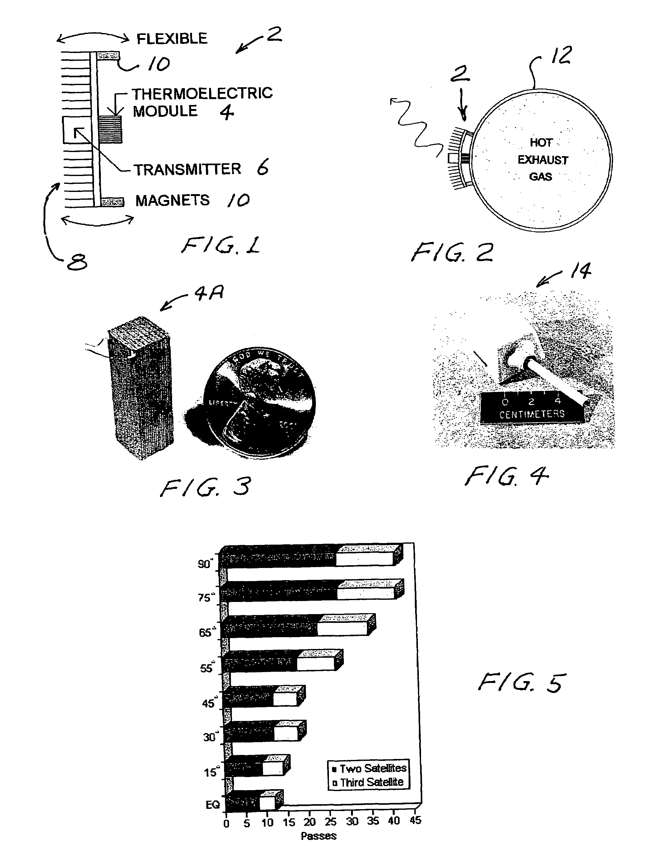
[0013]In a first preferred embodiment of the present invention a small thermoelectric module is attached to an exhaust pipe of a motor vehicle. The electrical power generated by the thermoelectric module is used to power a tracking transmitter. The thermoelectric module in this embodiment only provides power to the transmitter while the vehicle is operating. This is normally sufficient for tracking purposes because a stationary vehicle does not need to be tracked.

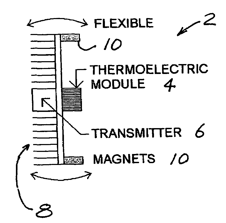
[0014]The tracking device 2 as shown in FIGS. 1 and 2 consists of one thermoelectric module 4, one transmitter 6, a flexible finned plate 8 for dissipating heat, and two high Curie temperature magnets 10 for attaching the device to the vehicle's tail pipe 12. Kapton sheets (not shown) are used to provide electrical insulation between the module and the tail pipe and the flexible finned plate. Kapton is preferred for this purpose since it has the unusual dual properties of high electrical resistivity and low thermal resistiv...


PUM


Abstract

A tracking device for tracking a vehicle in which a radio transmitter is powered by heat energy of the exhaust system of an engine propelling the vehicle. A thermoelectric module is attached to a hot portion of the exhaust system. Electrical power generated by the thermoelectric module is used to power the transmitter. A preferred tracking device consists of one thermoelectric module, one transmitter, a flexible finned plate for dissipating heat, and two high Curie temperature magnets for attaching the device to the vehicle's tail pipe. The transmitter is mounted on the flexible finned plate with a thermal insulator in-between them.

Description

[0001]This application is a continuation in part of Ser. No. 10 / 021,097 now U.S. Pat. No. 6,828,579 filed Dec. 12, 2001 which is incorporated herein by reference and also claims the benefit of Provisional Application Ser. No. 60 / 460,057 filed Apr. 3, 2003. The present invention relates to tracking devices and in particular to power sources for tracking devices.BACKGROUND OF THE INVENTION[0002]A well-known use for thermoelectric devices is for the extraction of electric power from waste heat. For example, U.S. Pat. No. 6,527,548 discloses a self powered space heater for a truck in which heat energy for the heater is used to power electric components of the heater plus charge a battery. In U.S. Pat. No. 6,053,163 heat from a stovepipe is used to generate electricity. U.S. Pat. No. 6,019,098 discloses a self-powered furnace. Various types of thermoelectric modules are available. A very reliable thermoelectric module with a gap-less egg-crate design capable of high-temperature operation...

Claims


Application Information

Patent Timeline
IPC IPC(8): G08G1/123H01L29/15H01L35/22H01L35/32
CPCH01L29/155H01L35/32H01L35/22H10N10/855H10N10/17
Inventor HILLER, NATHAN D.BASS, JOHN C.ALLEN, DANIEL T.
Owner HI Z TECH
Why Eureka
Eureka Blog
Learn More