Method and device for transcranial magnetic stimulation

Inactive Publication Date: 2006-03-07
BRAINLAB
View PDF29 Cites 114 Cited by
  • Summary
  • Abstract
  • Description
  • Claims
  • Application Information

AI Technical Summary

Benefits of technology

[0007]It is an object of the present invention to propose a method and a device for stimulating specific areas of a brain, by which application may be simplified and the spatial accuracy in stimulating and therefore in localising specific areas of the brain may be improved.
[0010]In accordance with a further aspect of the present invention, a simulation model is produced of the head to be examined, wherein the data determined from recording the head's 
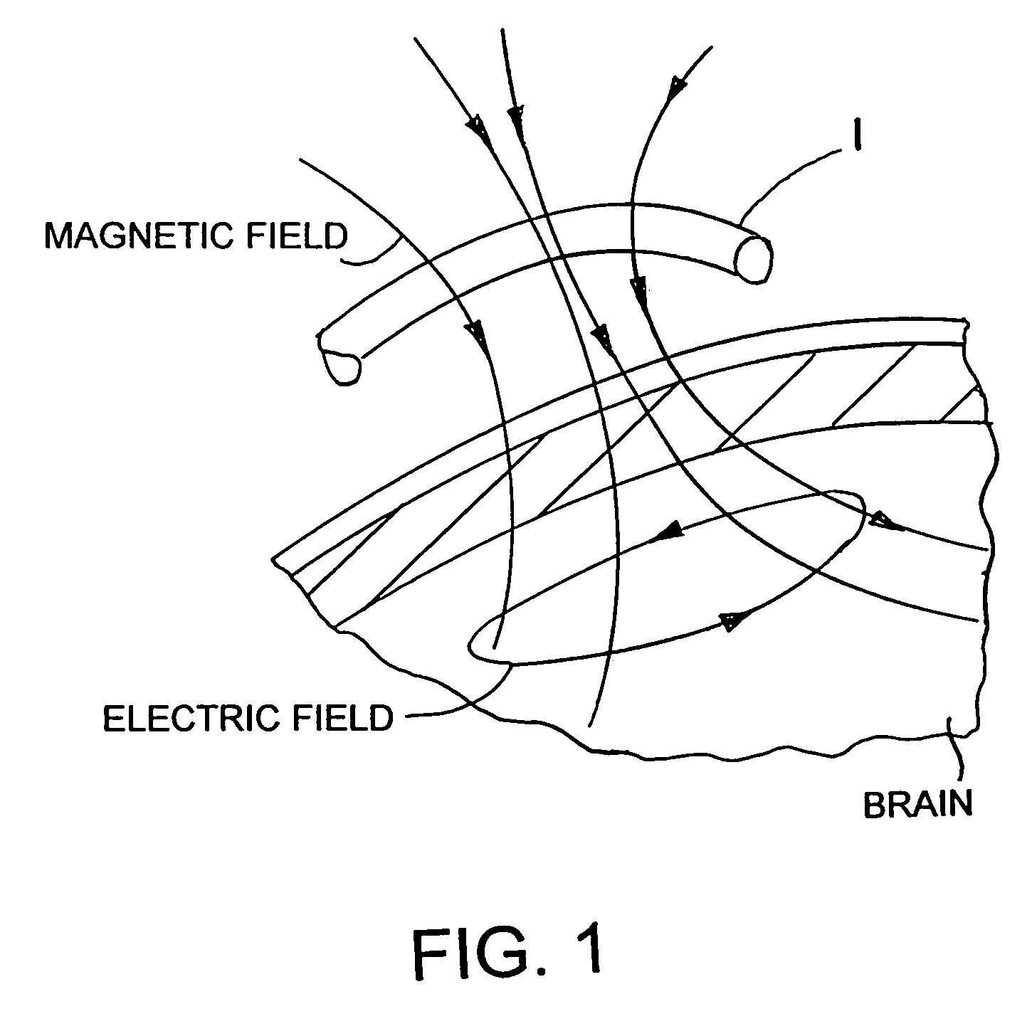
spatial structure may be used to improve the simulation model. The electrical or magnetic field generated by the induction device can thereby be relatively exactly focussed on a specific point in the brain by suitably positioning the induction device, since the layers over the brain which exhibit different conductivities act like various dielectrics which have a decisive influence on focusing the field on the brain.
[0011]The two methods described above for analysing and simulating the induction device and for modelling the head may be used separately or in combination, to further improve focussing the field generated by the induction device.
[0012]Using the method in accordance with the invention, transcranial magnetic stimulation (TMS) may be improved, and in particular made more precise, which enables specific areas of the brain, for example the aforementioned primary areas of the brain, to be precisely and non-invasively localised, which may for example improve pre-operative surgical planning. The methods in accordance with the invention may however also be used to examine or cure other brain dysfunctions, such as for example for diagnosing epilepsy or Parkinson's disease. By using the methods in accordance with the invention, it is possible to map brain functions exactly via an indirect method without having to open a person's cranium in order to directly access the brain.
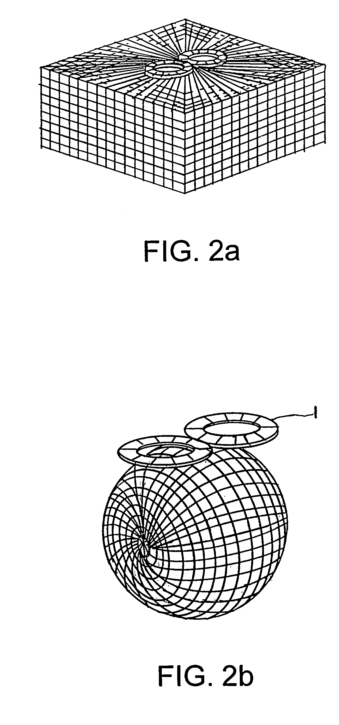
[0013]The head is advantageously modelled by building a finite, multi-shelled model wherein electrical and / or magnetic fields for example may be calculated using finite-element methods and the individual shells advantageously modelled for example as nested spherical or ellipsoid shells with adjustable thicknesses, which may for instance be arranged concentrically. The model is particularly advantageously sub-divided into three shells, wherein the respective shells from the outermost in simulate the scalp, the cranial bones and the surface of the brain. These three different areas of the head exhibit different electrical and magnetic characteristics, such that modelling a head using three shells with for example different dielectric constants and / or different conductivities may for example provide very good results if the values used for the electrical and / or magnetic parameters come as close as possible to values determined or calculated in experiments. The shell model is also advantageously modified according to the recorded spatial structure of a head to be examined, wherein the shell model is adapted as exactly as possible to the geometry of a head to be examined, for example by extending and / or distorting or shifting individual shells.
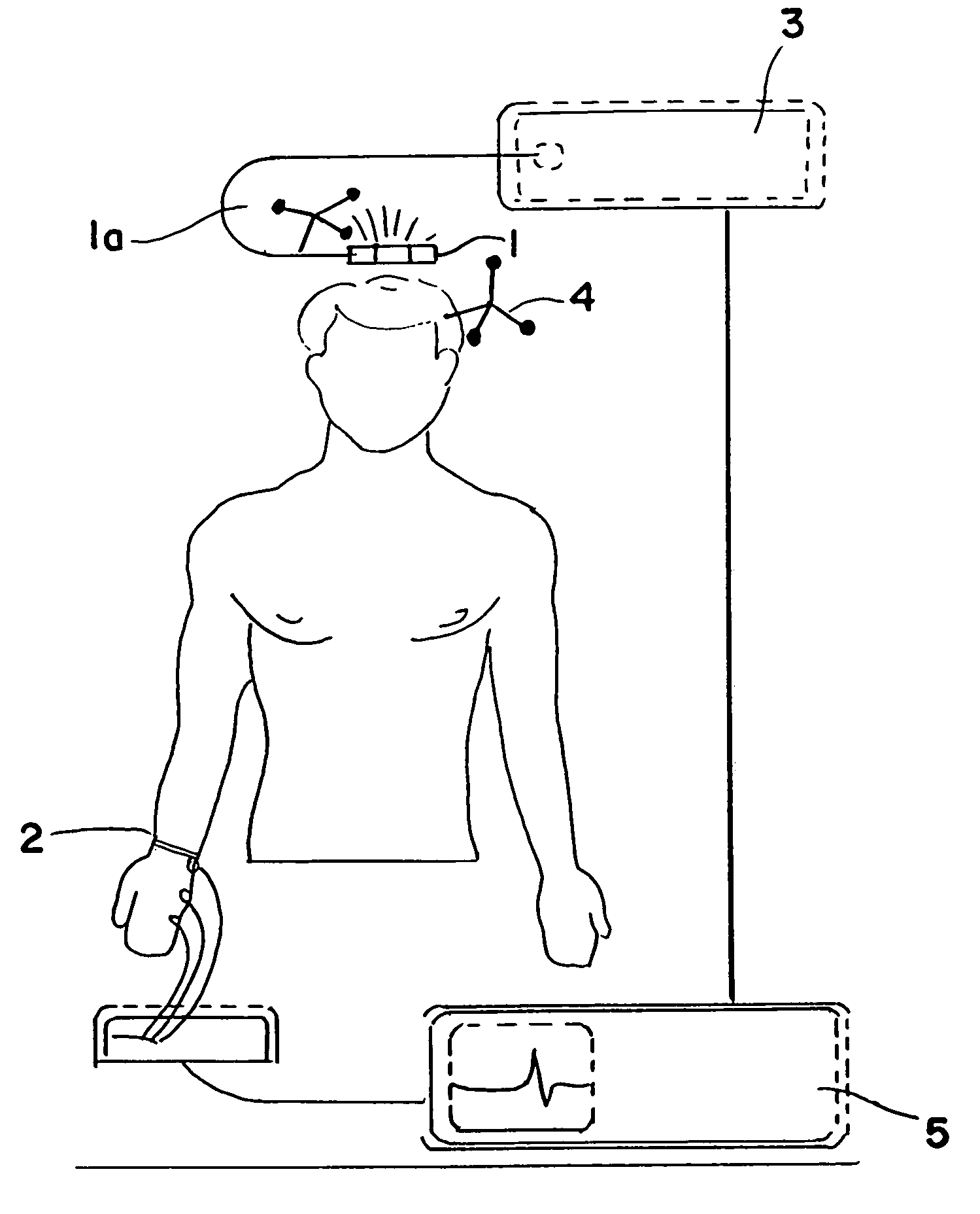
[0014]Preferably, markers—particularly preferably, passive markers—are arranged on the head to be examined and / or on the induction device, in order to be able to track the induction device and / or the head. Referencing and tracking persons and / or instruments is known from the prior art and will not be described here in detail. The induction device and head are matched in order to thus be able to determine the relative position of the induction device and the head as precisely as possible. Using markers has the advantage that a person under examination does not have to be securely positioned, but rather specific areas of the brain can still be precisely stimulated, even for a person moving freely around a room.

Problems solved by technology

However, this method can only be performed intra-operatively, the person under examination being fully conscious.
This, however, can lead to problems in the application of this method, since this is an unpleasant state for the person being examined, and if complications arise, the person cannot simply be laid down and made to relax, due to the exposed cranium.
Furthermore, various indirect methods are known for mapping brain functions, by which, however, only a considerably lower accuracy in locating specific areas of the brain may be achieved.
However, as mentioned above, this method is relatively imprecise and only provides spatial resolution in the range 0.5 to 1.0 cm.

Method used


Image

  • Method and device for transcranial magnetic stimulation
  • Method and device for transcranial magnetic stimulation
  • Method and device for transcranial magnetic stimulation

Examples


Embodiment Construction

[0033]FIG. 1 shows in diagram form a three-shell model of a head in accordance with the invention, wherein: the outer shell I models the scalp; beneath the scalp modelled by the outer shell I lies the second shell II which models the cranial bones. The inner area of the three-shell model is formed by the brain or surface of the brain III. A current in the induction device 1, shown schematically as a coil, creates the schematically shown magnetic field which comes out of the induction device and passes through the scalp and through the cranial bones, in order to induce an electrical field in the brain (these respectively modelled by the three shells I, II and III), which causes a ring-shaped flow of current by which a specific area of the brain is stimulated. Modelling the scalp, cranial bones and brain using two outer shells I and II surrounding the modelled brain III enables the induction device 1 to be positioned at a specific point, at a specific distance from the brain and at a ...


PUM


Abstract

The invention relates to a method for stimulating specific areas of a brain using an induction device, comprising the following steps: recording the spatial structure of the head, in particular the brain; generating a simulation model of the induction device; and arranging the induction device relative to the head such that a specific area of the brain determined by means of the simulation model of the induction device is stimulated by a current flowing in the induction device, as well as to a method for stimulating specific areas of a brain using an induction device, comprising the following steps: recording the spatial structure of the head, in particular the brain; generating a simulation model of the head; and arranging the induction device relative to the head such that a specific area of the brain determined by means of the simulation model of the head is stimulated by a current flowing in the induction device, as well as to a device for stimulating specific areas of a brain using an induction device connected to a marker.

Description

RELATED APPLICATION DATA[0001]This application is a continuation of U.S. patent application Ser. No. 10 / 003,476 filed on Nov. 1, 2001 now U.S. Pat. No. 6,827,681, which is incorporated herein by reference in its entirety.FIELD OF THE INVENTION[0002]The present invention relates to a method and a device for transcranial stimulation, in particular for non-invasively localising specific areas of the brain, such as for example the so-called primary areas of the brain. In this way, for instance, brain functions may be mapped, i.e. assigned to specific areas of the brain.BACKGROUND OF THE INVENTION[0003]In various areas of medicine, such as for example neurology, psychiatry or brain surgery, it is desirable to be able to localise specific functional areas of the brain in order to be able to map brain functions. If, for example, a brain tumour is to be removed by surgery, then as far as possible the tumour should be removed without, however, possibly damaging the so-called primary areas of...

Claims


Application Information

Patent Timeline
IPC IPC(8): A61N2/00A61B5/0484A61B5/055A61N2/02A61N2/04
CPCA61N2/02A61B5/055A61B5/0484A61B5/377
Inventor TANNER, PHILLIPPHARTLEP, ANDREASWIST, HENRIKWENDICKE, KERSTINWEYH, THOMAS
Owner BRAINLAB
Why Eureka
Try Eureka