
Electrically operable pivoting actuator for door mirror of motor vehicle

a technology of electric operability and actuator, which is applied in the direction of instruments, machine supports, other domestic objects, etc., can solve the problems of relatively high manufacturing cost and inability to manufacture a mass production of the above-mentioned electrically operable pivoting actuator, and achieve the effect of relatively low manufacturing cos

Inactive Publication Date: 2006-03-07
CHAW KHONG TECH
View PDF7 Cites 27 Cited by
  • Summary
  • Abstract
  • Description
  • Claims
  • Application Information

AI Technical Summary

Benefits of technology

"The present invention provides an electrically operable pivoting actuator for the door mirror of a motor vehicle. The actuator is designed to be large-scale and low-cost. It can be installed in a variety of door mirrors without modifications. The actuator includes a frame with a channel, top groove, and transmission system, as well as idler gears, coupling gear wheel, and resilient means. There is also an annular lower groove and raised stop in the frame. A cover with the top groove and transmission system contains an electromotor with a driven worm. A coupling member is secured onto a support of the door mirror and has two protuberances for stopping the rotation of the coupling member. A shaft member with protrusions is inserted into the coupling gear wheel. The lower groove has inner and outer ring segments-shaped grooves and an abutment ring secured onto the coupling member. The actuator allows for a predetermined angle of the fold-in door mirror and also allows for a predetermined angle of the fold-out door mirror."

Problems solved by technology

In other words, mass production of a door mirror having the above electrically operable pivoting actuator is made impossible.
As a result, the manufacturing cost is relatively high.

Method used


Image

  • Electrically operable pivoting actuator for door mirror of motor vehicle
  • Electrically operable pivoting actuator for door mirror of motor vehicle
  • Electrically operable pivoting actuator for door mirror of motor vehicle

Examples


Embodiment Construction

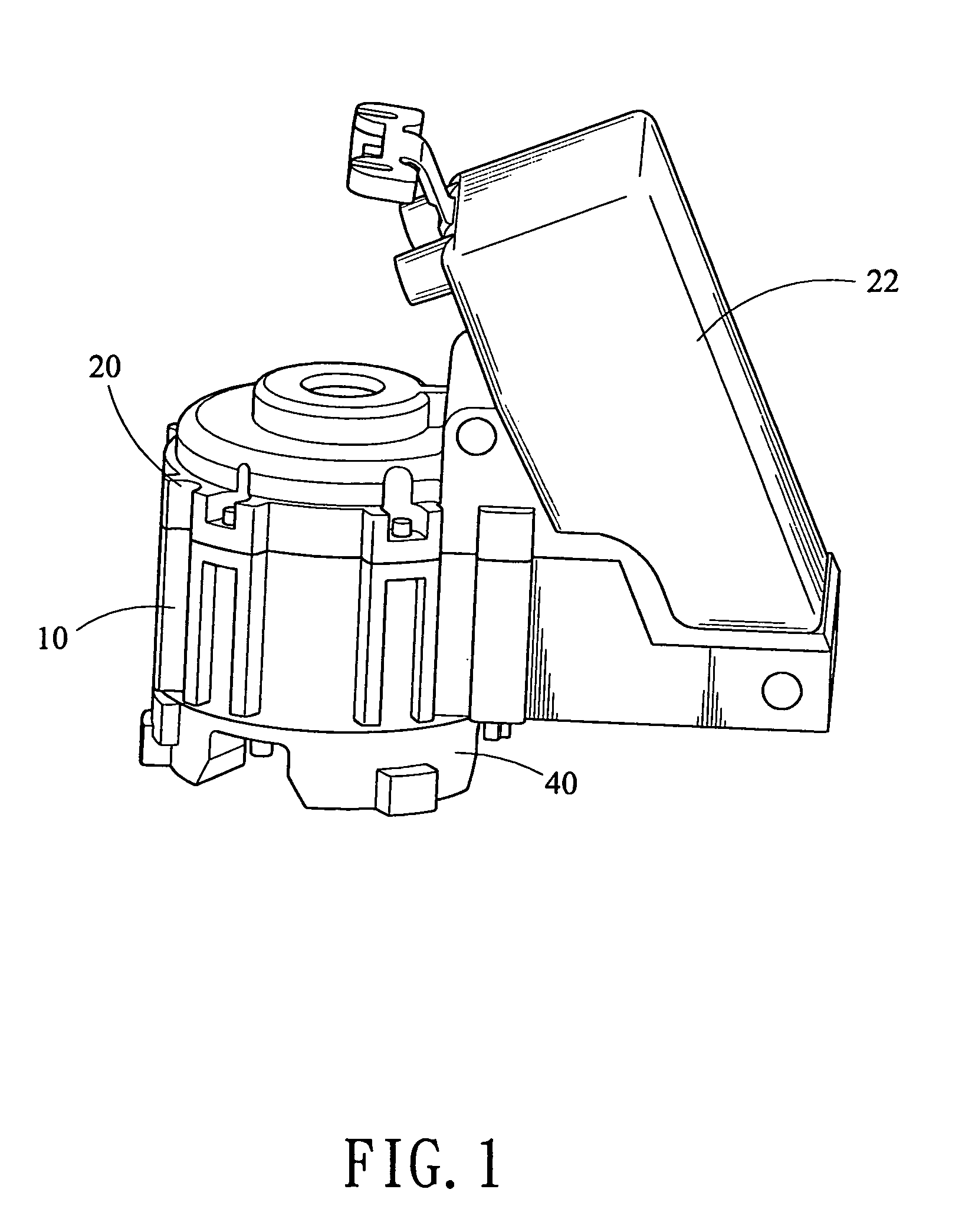
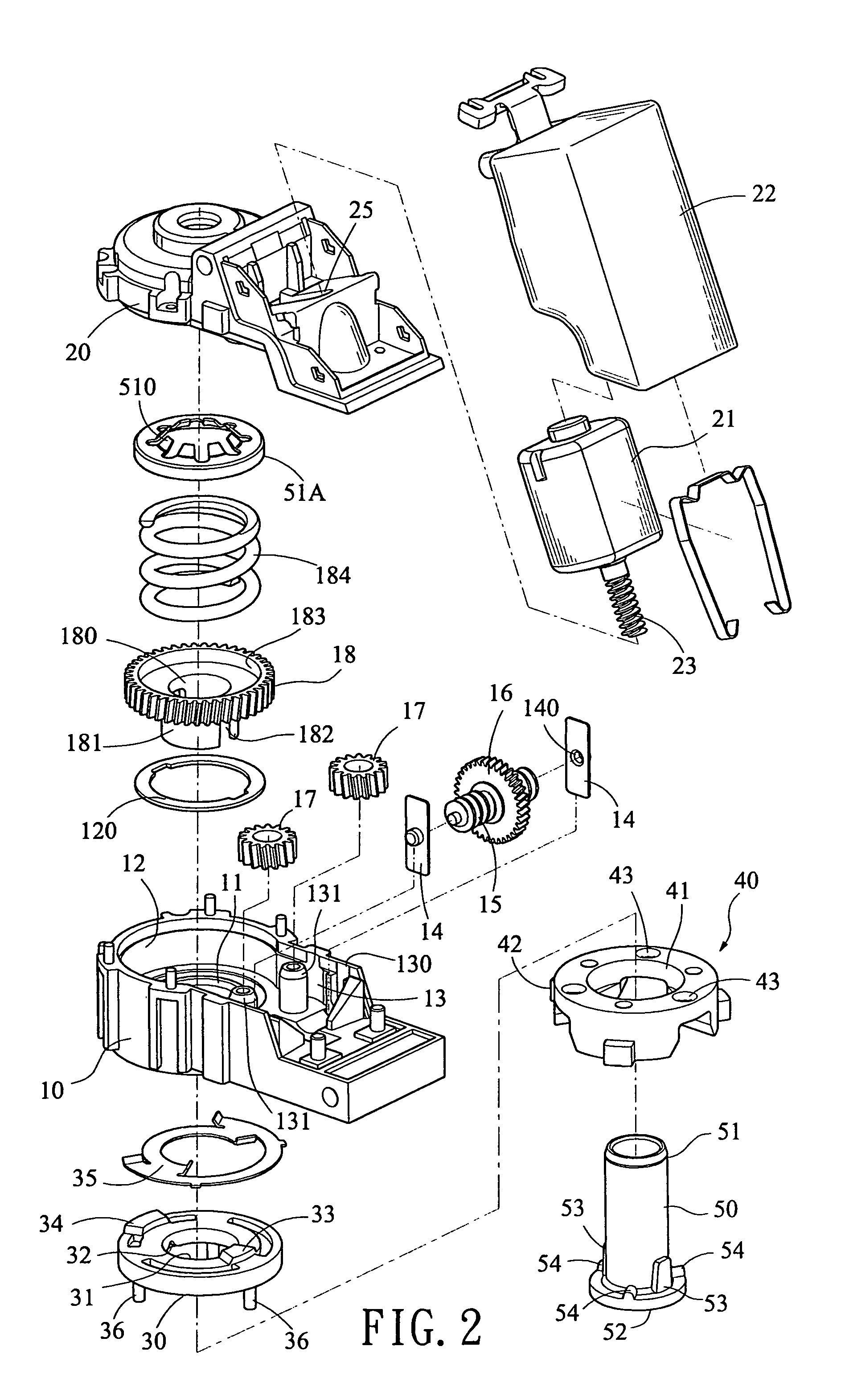
[0030]Referring to FIGS. 1 to 9, there is shown an electrically operable pivoting mechanism for the door mirror of a motor vehicle in accordance with the invention. Each component of the invention will be described in detail below.

[0031]A frame 10 having an annular frame part and a rectangular frame part, comprises a channel 11 (see FIG. 3) at the annular frame part, an annular top groove 12 around a top portion of the channel 11, a top cavity 13 in the rectangular frame part and at a side of the top groove 12 and in communication with the top groove 12, two vertical recesses 130 at both sides of the top cavity 13, two rectangular supporting plates 14 having a central aperture 140 fitted in the recesses 130, a worm 15 pivotably supported between the supporting plates 14 by inserting in the apertures 140, a worm wheel 16 formed around the worm 15, two posts 131 in the top cavity 13 near the recesses 130—130 and between the top groove 12 and the worm 15, two idler gears 17 pivotably s...


PUM


Abstract

An electrically operable pivoting actuator for a door mirror is disclosed. The pivoting actuator comprises a frame, an electromotor, and an annular coupling member secured onto a horizontally extended support of the door mirror, the coupling member comprising two diametrically opposite protuberances wherein one protuberance is adapted to engage with a stop on the frame for stopping a clockwise or counterclockwise rotation of the coupling member relative to the frame so as to define a predetermined angle α of the fold-in door mirror as an angle between an extreme position of the stop engaged with one protuberance and another extreme position of the stop engaged with the other protuberance. The invention can be produced in a large scale for reducing the manufacturing cost and is adapted to install in any of a variety of door mirrors of motor vehicles without further modifications.

Description

BACKGROUND OF THE INVENTION[0001]1. Field of the Invention[0002]The present invention relates to door mirrors of a motor vehicle and more particularly to an electrically operable pivoting actuator for the door mirror of the motor vehicle.[0003]2. Description of Related Art[0004]Folding of the door mirror relative to a motor vehicle is necessary in many situations. A folding over of the door mirror relative to the body of the car is occurred when, for example, an obstacle hits the door mirror from a rear position in which an angle from the fold-over position of the door mirror to the normal, operational position is defined as angle β. Further, a folding in of the door mirror relative to the body of the car is occurred when, for example, parking in a narrow space in which an angle from the normal, operational position to the fold-in position of the door mirror is defined as angle α.[0005]Designs about angle α and angles β are well known. For instance, U.S. Pat. No. 6,130,514 disclosed...

Claims


Application Information

Patent Timeline
Patent Type & Authority Patents(United States)
IPC IPC(8): B60R1/07B60R1/074
CPCB60R1/074
Inventor HSU, CHIH-PANG
Owner CHAW KHONG TECH
Learn More