
Reader for electro-optically reading indicia through vertical window at which full coverage, omni-directional scan pattern is generated

a vertical window and reader technology, applied in the field of electro-optically reading indicia, can solve the problems of insufficient work space, inability to read symbols in the picket fence, and difficulty in blind aiming of symbols

Inactive Publication Date: 2006-03-07
SYMBOL TECH LLC
View PDF10 Cites 4 Cited by
  • Summary
  • Abstract
  • Description
  • Claims
  • Application Information

AI Technical Summary

Benefits of technology

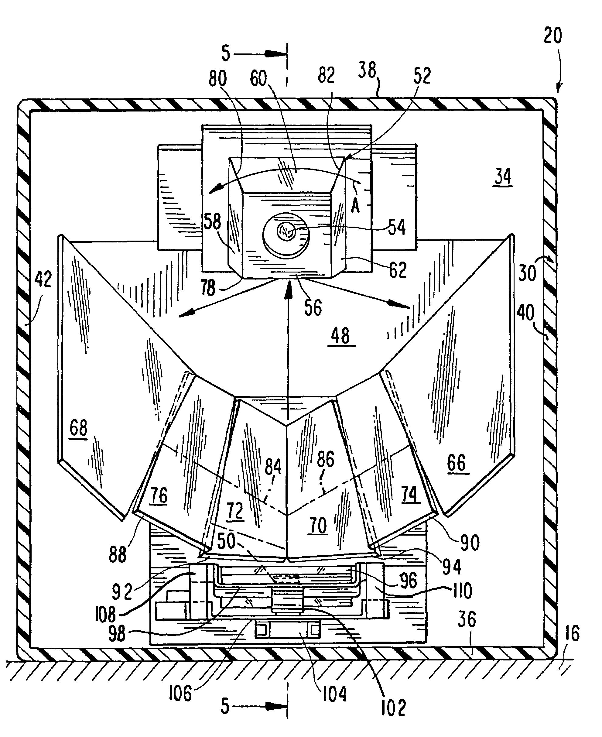
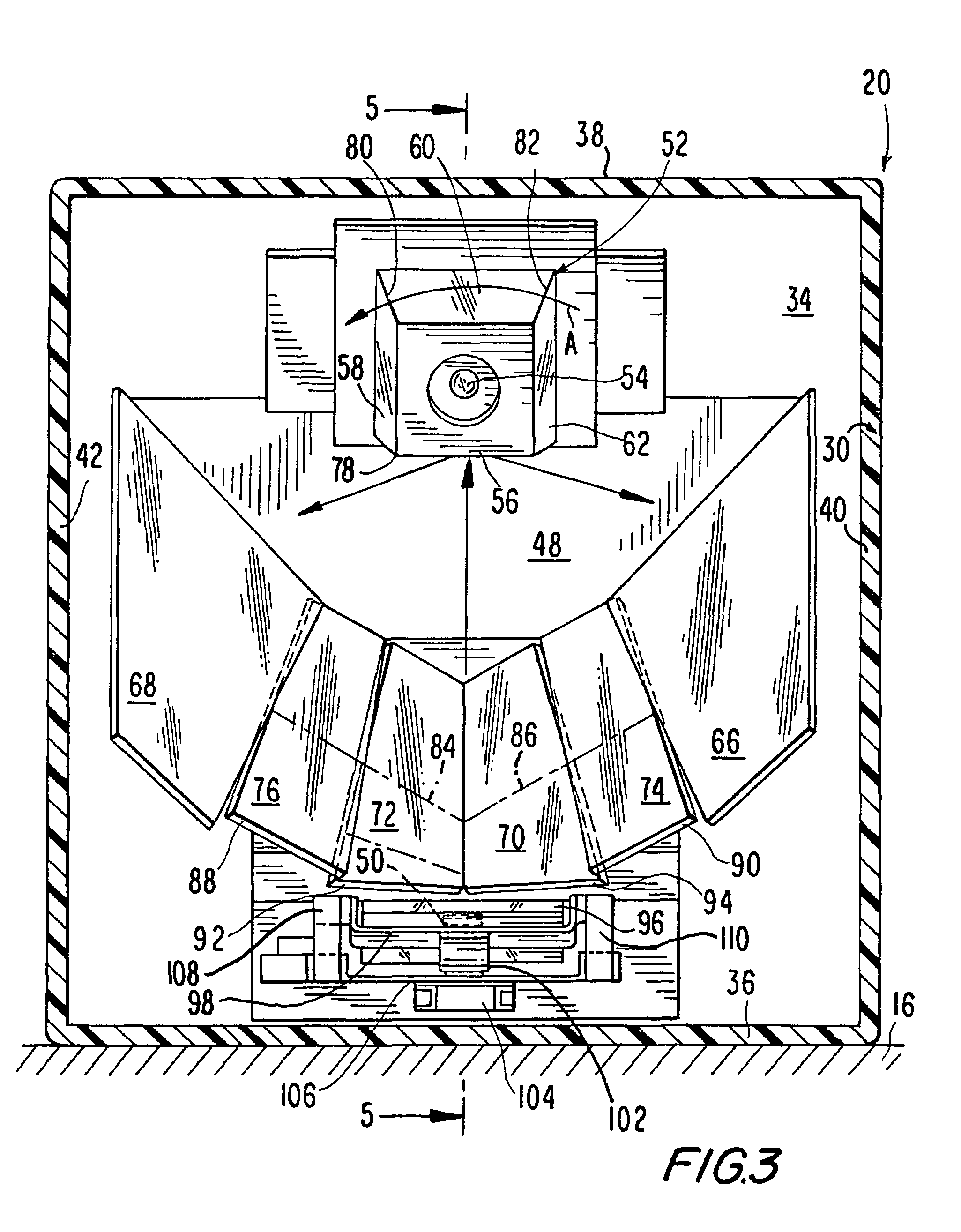
This patent describes a vertical slot scanner that can generate a full scan pattern with no dead zones. The scanner uses a rotating mirror and a set of folding mirrors to create a scan pattern that covers the entire window. The scanner also includes a third pair of mirrors that reflects scan lines at the upper central region of the window, eliminating a prior art dead zone. The invention aims to improve the state of the art of vertical slot scanners and increase the likelihood of reading indicia of random orientation.

Problems solved by technology

The blind-aiming of the symbol is made more difficult because the position and orientation of the symbol are variable.
In some installations of a vertical slot scanner, there is insufficient available work space to slide products across the countertop in front of the vertical window, in which case, the operator will typically present the symbol by holding the product more or less stationary in front of the vertical window.
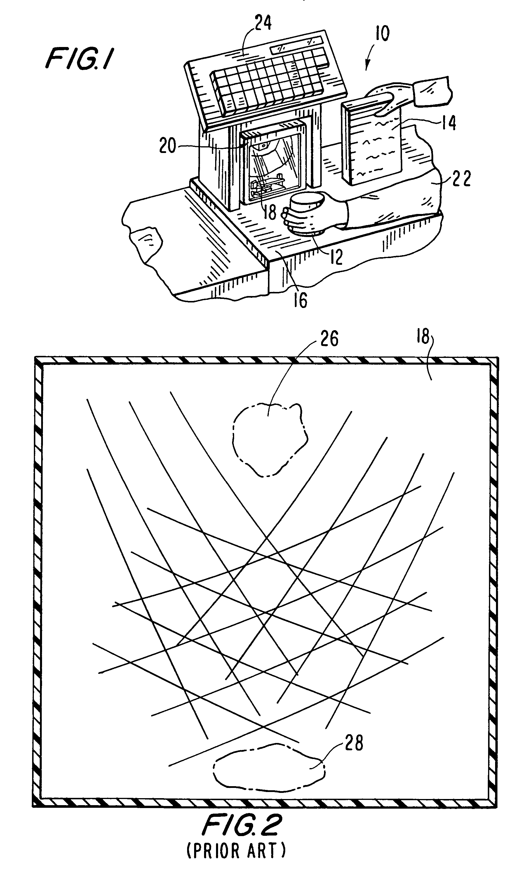
Yet, the known vertical slot scanners have “dead zones” empty of scan lines at upper central regions of the vertical windows and thus cannot read symbols in the picket fence orientation when the symbols are located above the central regions of the windows.
Some of the known vertical slot scanners also have such dead zones at lower central regions of the vertical windows and thus cannot read symbols in the picket fence orientation when the symbols are located below the center regions of the windows.
These dead zones result in some products not being read the first time that they are slid past, or presented to, the window, thereby slowing down transaction processing and reducing productivity.
However, as noted above, the scan pattern of the prior art vertical slot scanner does not entirely fill the vertical window and has dead zones, especially above and below the central region of the vertical window, which limit reader performance.

Method used


Image

  • Reader for electro-optically reading indicia through vertical window at which full coverage, omni-directional scan pattern is generated
  • Reader for electro-optically reading indicia through vertical window at which full coverage, omni-directional scan pattern is generated
  • Reader for electro-optically reading indicia through vertical window at which full coverage, omni-directional scan pattern is generated

Examples


Embodiment Construction

[0027]Reference numeral 10 generally identifies a workstation for processing transactions and specifically a checkout counter at a retail site at which products, such as a can 12 or a box 14, each bearing a bar code symbol, are processed for purchase. The counter includes a countertop 16 across which the products are slid past a vertical window 18 of a vertical slot reader 20 mounted on the countertop 16. A checkout clerk or operator 22 is located at one side of the countertop, and the reader 20 is located at the opposite side. A cash / credit register 24 is located within easy reach of the operator.

[0028]As described in detail below, a scan pattern generator within the reader 20 generates a scan pattern at the window 18, and projects the scan pattern into space away from the reader in an outward direction toward the operator. The scan pattern is comprised of multiple scan lines, at least one of which is intended to sweep over at least part of a symbol associated with, and typically p...


PUM


Abstract

A vertical slot scanner generates a full coverage scan pattern for reading symbols presented or moved past a vertical window. Scan lines are generated in upper and lower central regions of the window to improve scanner productivity.

Description

BACKGROUND OF THE INVENTION[0001]1. Field of the Invention[0002]The present invention generally relates to an electro-optical reader for reading indicia such as a bar code symbol and, more particularly, to generating a full coverage, omni-directional scan pattern at a vertical window of the reader to insure reliable reading of the symbol through the window.[0003]2. Description of the Related Art[0004]Flat bed laser readers, also known as horizontal slot scanners, have been used to electro-optically read bar code symbols, particularly of the Universal Product Code (UPC) type, at a point-of-transaction workstation in supermarkets, warehouse clubs, department stores, and other kinds of retailers for many years. As exemplified by U.S. Pat. Nos. 5,059,779; 5,124,539 and 5,200,599, a single, horizontal window is set flush with, and built into, a horizontal countertop of the workstation. Products to be purchased bear an identifying symbol and are slid across the horizontal window through w...

Claims


Application Information

Patent Timeline
Patent Type & Authority Patents(United States)
IPC IPC(8): G06K7/10G02B26/10G06V30/224G02B26/12G07G1/00
CPCG06K7/10693G06K7/10623G06K7/10
Inventor BARKAN, EDWARDSHEPARD, HOWARD
Owner SYMBOL TECH LLC
Learn More