Eureka AIR delivers breakthrough ideas for toughest innovation challenges, trusted by R&D personnel around the world.

Keyboard and a method for manufacturing it

a manufacturing method and keyboard technology, applied in the field of keys, can solve the problems of complex structure of the keyboard, a large space occupation, and a lot of space occupation, and achieve the effects of simple structure, thin and simple keyboard structure, and easy manufacturing

Inactive Publication Date: 2006-02-28
NOKIA CORP
View PDF28 Cites 37 Cited by
  • Summary
  • Abstract
  • Description
  • Claims
  • Application Information

AI Technical Summary

Benefits of technology

[0009]An advantage of the invention is that the keyboard structure is simple and thus also reliable and easy to manufacture. Further, the user receives clear tactile feedback from the keyboard. The keyboard structure is thin and simple, because separate rigid key tops are not needed. Further, owing to the hinge in a key, the course of movement of the key is very accurate. The flap forming the key can be made rather big in size, in which case it has a lot of space for the key graphics. The key can be lifted upwards from its free end, but it still stays in its place, and owing to its structure the lifted key returns to its original position. All in all, the keys of the keyboard are firm and stay securely in desired places, whereby the appearance and ergonomics of the keyboard remain good.
[0010]The invention will be explained in more detail in connection with the attached drawings, of which
[0011]FIG. 1 shows a schematic top view of a part of a keyboard;
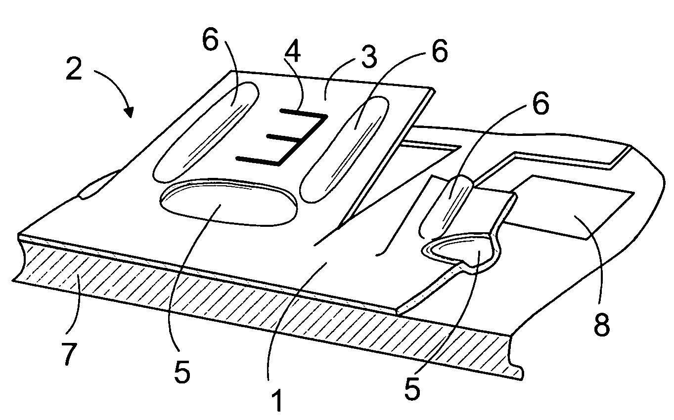
[0012]FIG. 2 shows a schematic perspective view and partial section of keys;
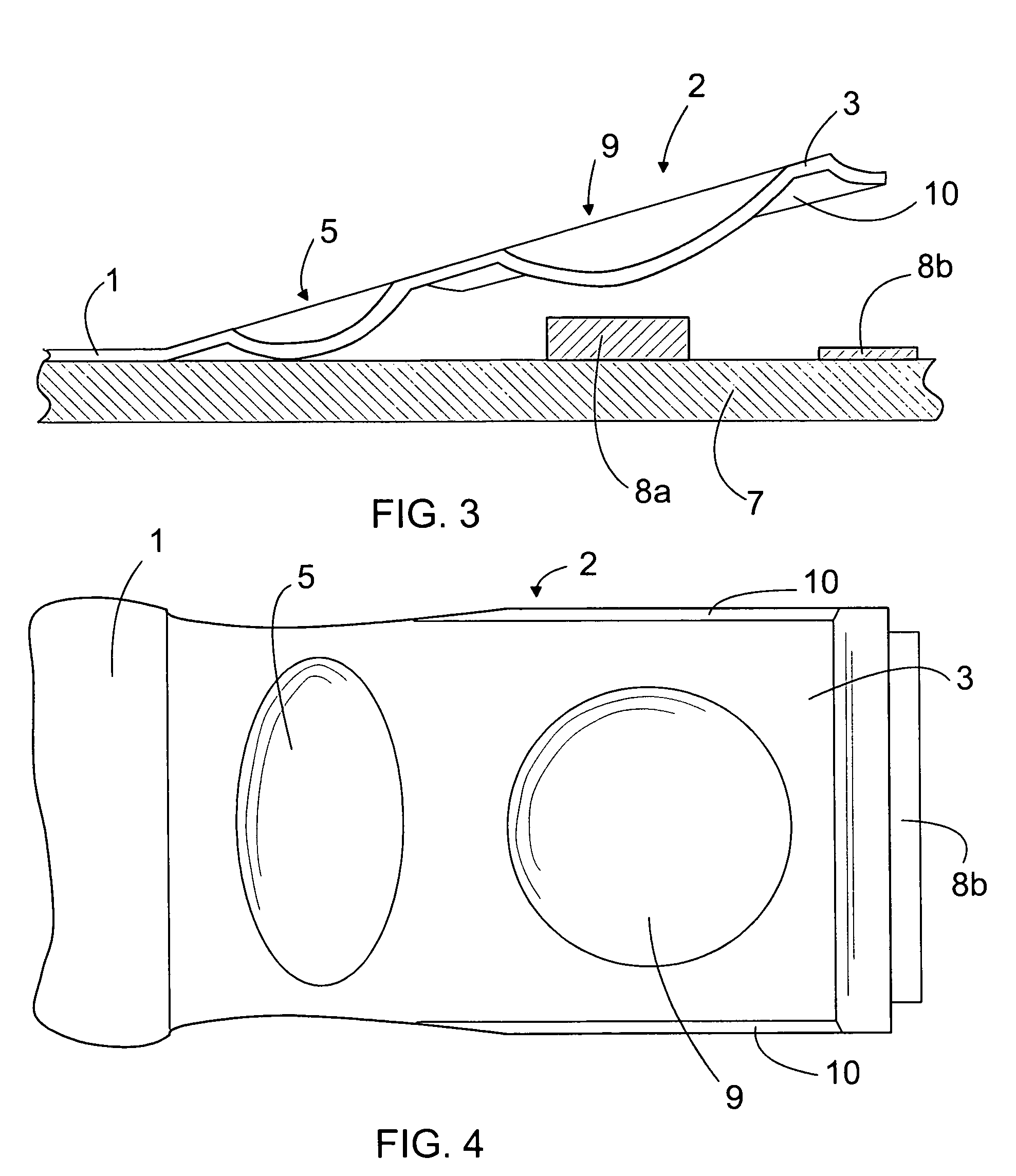
[0013]FIG. 3 shows a schematic side view and cross-section of a second embodiment of a key;
[0014]FIG. 4 shows a schematic top view of the key according to FIG. 3;

Problems solved by technology

Such a keyboard structure is complex and takes a lot of space, and in addition, it is rather difficult to manufacture.
The structure of the keyboard is complex and contains several layers.
Therefore, the keyboard is rather difficult to manufacture.
Further, the space available for the key graphics on the upper surface of the keys is relatively small.

Method used


Image

  • Keyboard and a method for manufacturing it
  • Keyboard and a method for manufacturing it
  • Keyboard and a method for manufacturing it

Examples


Embodiment Construction

[0018]FIG. 1 shows a keyboard frame sheet 1, which comprises keys 2. The structure of the keys is also illustrated in FIG. 2. For the sake of clarity, the key 2 on the right side is shown cut and in cross-section in FIG. 2.

[0019]The key 2 comprises a flap 3. The upper surface of the flap 3 indicates key graphics 4, i.e. a number, letter and / or other character or sign entering of which is provided by depressing the key.

[0020]The keyboard is formed by forming first a sheet of a size of the whole keyboard or at least several keys 2. The sheet can be a steel sheet, for example. The steel sheet can be of spring steel, for example. The thickness of the steel sheet can be, for instance, 0.05 to 0.30 mm. For example, the thickness of the steel sheet can be 0.15 mm. The sheet can be, instead of steel, of some other sufficiently elastic and durable material, such as rubber or other suitable material. A flap 3 is cut to the sheet, and a shallow and flat dent 5 is formed at the root of each fla...


PUM


Abstract

A keyboard comprising at least one flap forming a key, the flap being pressed against a contact point when depressed from above, and rising back after the depressing. The flap is attached by its one end to the frame sheet of the keyboard in such a way that this structure forms the hinge of the key. There is at least one buckling member in connection with the flap, and the flap is formed rigid. The keyboard may be formed in such a way, for example, that a keyboard frame sheet is formed, the flap forming the key is cut partially off the keyboard frame sheet, a buckling member is formed in connection with the flap, and the flap is lifted upwards from the surface of the frame sheet.

Description

BACKGROUND OF THE INVENTION[0001]The invention relates to a keyboard comprising at least one flap forming a key, and a contact point, the flap being pressed against the contact point when depressed from above, and rising back after the depressing.[0002]Further, the invention relates to a method for forming a keyboard.[0003]U.S. Pat. No. 4,480,937 discloses a keyboard having a metal sheet provided with leaf springs. The end of a leaf spring is flexible and is depressed with a plunger at the tip of which there is typically a key top. When the plunger is depressed, the contact cantilevers formed on the sides of the leaf spring get into contact with a contact surface, and after the depressing the leaf spring raises the plunger into the upper position. Such a keyboard structure is complex and takes a lot of space, and in addition, it is rather difficult to manufacture.[0004]U.S. Pat. No. 4,160,886 discloses a keyboard formed in a plastic sheet in such a way that the plastic sheet compris...

Claims


Application Information

Patent Timeline
Patent Type & Authority Patents(United States)
IPC IPC(8): H01H9/26H01H13/70
CPCH01H13/7013H01H2215/03H01H2215/034H01H2221/016H01H2233/002H01H2223/0345H01H2225/018H01H2229/05H01H2221/044
Inventor PIHLAJA, PEKKA
Owner NOKIA CORP
Why Eureka
Eureka Blog
Learn More