Eureka AIR delivers breakthrough ideas for toughest innovation challenges, trusted by R&D personnel around the world.

Developing apparatus including agitating member

a technology of developing apparatus and agitating member, which is applied in the direction of developers, electrographic process apparatus, instruments, etc., can solve the problems of deterioration of the flowability of the toner, image failure, and high hygroscopic property, and achieve the effect of superior low-temperature fixing property

Active Publication Date: 2006-02-21
CANON KK
View PDF11 Cites 12 Cited by
  • Summary
  • Abstract
  • Description
  • Claims
  • Application Information

AI Technical Summary

Benefits of technology

[0040]It is one objective of the present invention to provide a developing apparatus for performing developing using magnetic toner having a superior low-temperature fixing property.
[0041]It is another objective of the present invention to provide a developing apparatus that can prevent the deterioration of the flowability of toner.
[0042]It is an additional objective of the present invention to provide a developing apparatus having superior environmental stability.
[0043]It is a further objective of the present invention to provide a developing apparatus that can form a satisfactory image without having to generate an image failure during the long term usage.
[0044]It is a still further objective of the present invention to provide a developing apparatus that can appropriately circulate toner.
[0045]It is one more objective of the present invention to provide a developing apparatus that can store a large amount of toner and that is appropriate for a fast developing system.

Problems solved by technology

However, since polyester is highly hygroscopic and hydrophilic, in an environment at a high temperature and a high humidity, the flowability of the toner is deteriorated due to the hygroscopicity of the polyester resin, and various problems occur.
However, these two proposals are not related to the techniques employed for improving the hydrophobic property of polyester toner, and still more improvement is required for the flowability of toner in a high temperature and high humidity environment.
On the other hand, this may cause over-electrification in a low temperature and low humidity environment.
Therefore, especially in a high temperature and high humidity environment, the toner is not satisfactorily electrified and deterioration of the developing function occurs, which causes an image failure.
That is, when wetting of a toner tends to occur at a low density, it means that its hygroscopic property is high.
As less magnetic iron oxide is exposed on the surface of the toner particles, i.e., when more of the surface of the toner particle is covered with the bonding resin component, the wetting of the magnetic toner occurs at a high methanol concentration, i.e., wetting of the toner is not easy.
When more magnetic iron oxide is exposed on the surface of the toner particles, the electrification capability is reduced and the wettability is deteriorated, so that in a high temperature and high humidity environment, the flowability of the toner tends to be deteriorated.
In other words, in order to prevent the magnetic toner from being over-charged in a low temperature and low humidity environment, and to stabilize the long term electrification of the toner, the magnetic iron oxide on the surface of the toner particles must be exposed and dispersed, to a degree; however, the magnetic iron oxide exposed on the surface of the toner particles deteriorates both the wettability of the toner and the flowability of the toner in a high temperature and high humidity environment.
Especially for a fast developing system that stores a large amount of toner, since from the viewpoint of image fixing at a low temperature, polyester toner must be employed, the flowability of toner in a high temperature and high humidity environment is more remarkably deteriorated due to hygroscopicity (hydrophile), and the following problems occur.
As a first problem, since toner is not uniformly supplied to a developing roller that is a developer carrying member for carrying toner from a toner container to a photosensitive member, an image failure, such as fading, occurs.
As a second problem, since toner that is scraped from the developing roller by a regulating member remains on the reverse side of the developing roller, and since over-charging occurs because of the continuous fiction of the toner against the developing roller, a reduction in image density and an image failure such as fogging occur.
As a third problem, since a toner that cannot be circulated due to poor flowability is maintained on the reverse side of the developing roller, and since the toner is subjected to friction heat generated near the developing roller, the toner is thermally damaged (toner deterioration) and an image failure occurs.
As a fourth problem, since packing for toner having poor flowability tends to occur due to the weight of the toner in a large toner container, and when toner in this state is retained in an environment at a high temperature and a high humidity, blocking in the toner container will occur.
However, since the flowability improvement techniques disclosed in Japanese Patent Application Laid-Open Nos. 7-281478, 2000-284522 and 6-230604 respectively provide for the changing of the property of the resin, by changing the flowability of the wax contained in the toner particles, and by changing the flowability index of the magnetic member, the properties of various toner materials can be changed to obtain a desired toner index flowability, while the costs will be increased and a preferable development characteristic may not be obtained.
In addition, according to the method disclosed in Japanese Patent Application No. 2000-310884 for using an outward additive, while the outward additive is highly hydrophobic, it is difficult to say that the original hydrophobicity of the toner will be achieved because the state wherein the outward additive is dispersed across the surface of the toner particles will differ, depending on an outward additive type.
Especially for a fast developing system for which a large amount of toner is used, it is important that, when the toner usage term is long, a stable toner electrification amount be maintained without the toner characteristic being changed, and an improvement in the toner characteristic (hydrophobicity), using only the outward additive, will not be satisfactory.
Further, for a fast developing system requested for long-term use, it is not sufficient for a highly hydrophobic toner to be employed, and it goes without saying that optimization of the structure of the developing apparatus must be a requisite.
Furthermore, for the technique disclosed in Japanese Patent Application Laid-Open No. 2001-201931, wherein the toner container for the developing apparatus, in which a large amount of toner can be stored, is defined as including a plurality of chambers, and the toner is agitated and carried by agitating members, provided in the individual chambers, and an increase in the size of the toner container can not be avoided, and since multiple agitating members are required, the size and the costs will also be increased.
According to this method, however, since both the driving means and the control means are required, the size and the cost of the developing apparatus are also increased.

Method used


Image

  • Developing apparatus including agitating member
  • Developing apparatus including agitating member
  • Developing apparatus including agitating member

Examples


first experiment

[0072]With this arrangement, in the environment at a low temperature and low humidity (15° C. and 10%) and in the environment at a high temperature and high humidity (30° C. and 80%), continuous printing was performed for an image pattern having the coverage rate of 2%. In any environment, the stable toner electrification amount was maintained during printing of about 200,000 sheets since the process cartridge C was initially used until the toner was exhausted, and satisfactory images could be obtained without reduction of the image density and image failures such as fogging and fading.

[0073]In an environment at a low temperature and low humidity and in an environment at a high temperature and high humidity, the amount q (μC / g) of charged toner carried by the developing roller 2 was measured by a 6514 electrometer by Casley Co., Ltd. using an aspiration method. The measurement results are shown in FIGS. 5 and 6, respectively. It is understood that, in either environment, near the va...

second embodiment

[0111]An image forming apparatus and toner used for a second embodiment are the same as those for the first embodiment.

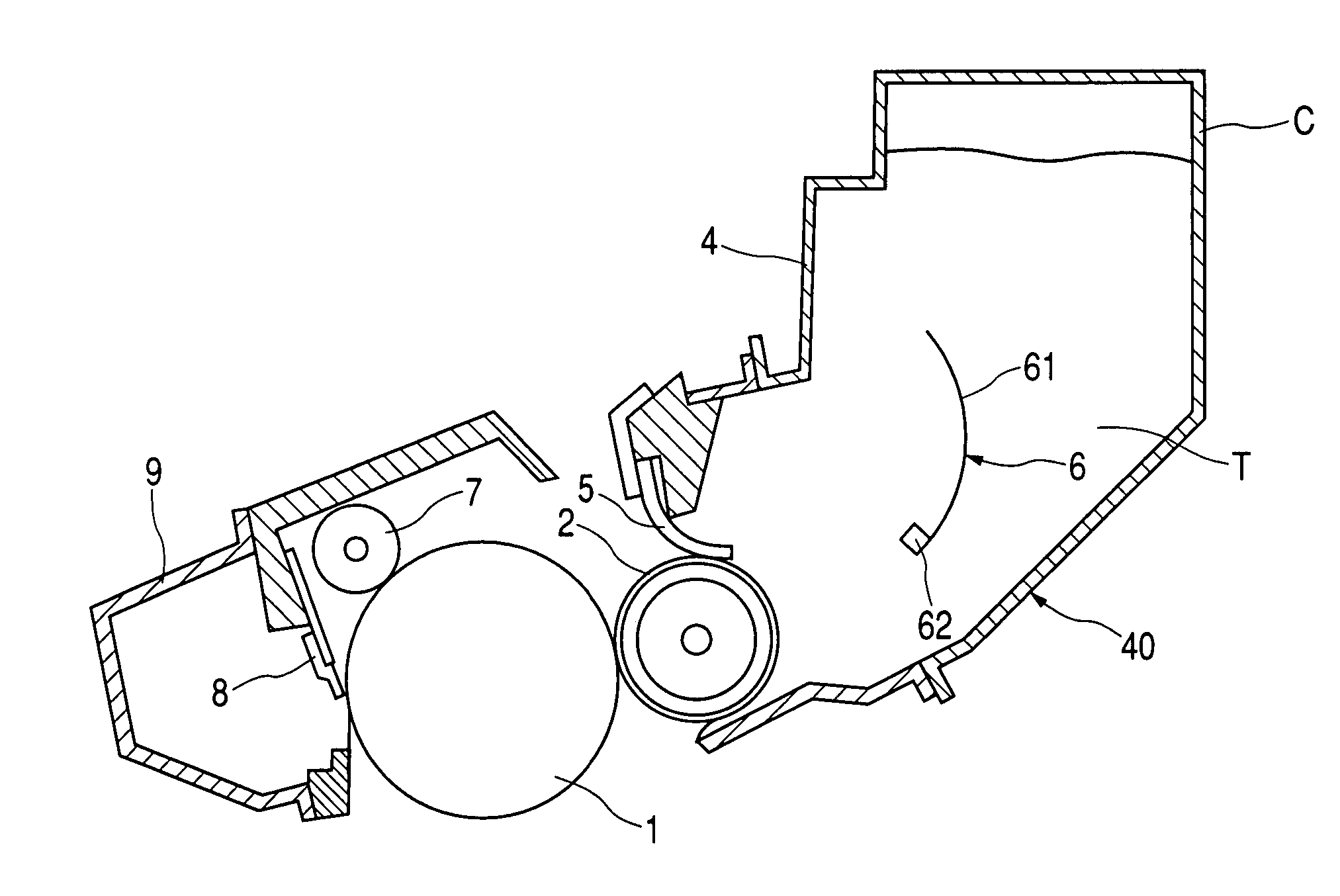
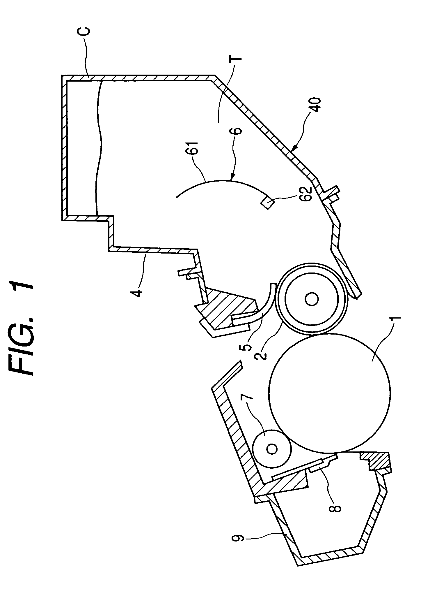
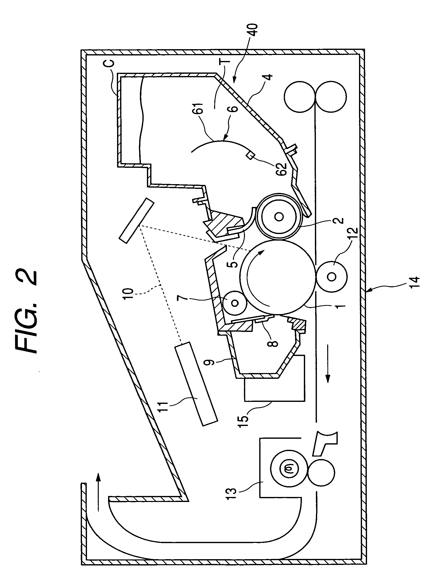
[0112]As is shown in FIG. 7, a developing apparatus 40 according to the second embodiment has a feature that a larger amount of toner is stored and a plurality of agitating members 6a and 6b are provided for a toner container 4.

[0113]With this arrangement, the own weight of the toner can be dispersed, and the circulation of the toner in the toner container 4 can be increased. Therefore, the capacity of a process cartridge C can be more increased.

[0114]This embodiment is the same as the first embodiment, except in that the amount of loaded toner is 1500 (g), the rotation speed c of the agitating member 6a closer to a developing roller 2 is 0.525 (rps), and the rotation speed e of the agitating member 6b farther from the developing roller 2 is 0.25 (rps).

[0115]The rotation radii of the agitating members 6a and 6b are 40 mm, and as is shown in FIG. 4, these agitating m...


PUM


Abstract

A developing apparatus includes a rotatable, developer carrying body for carrying a one-component developer and a rotatable, agitating member for agitating the one-component developer. The one-component developer is magnetic toner at least containing a bonding resin and magnetic iron oxide. When wettability of the magnetic toner relative to a mixture solution of methanol and water is measured at the transmittance of light having a wavelength of 780 nm, a methanol concentration at the transmittance of 80% is within the range of 45 to 65 volume %, and wherein 0.1≦b / a≦0.2 is established where a (rps) denotes the rotation speed of the developer carrying body, and b (rps) denotes the rotation speed of the agitating member.

Description

BACKGROUND OF THE INVENTION[0001]1. Field of the Invention[0002]The present invention relates to a developing apparatus, preferably employed for an image processing apparatus that uses an electrophotographic system, and to a detachable processing cartridge, which is also employed for the image processing apparatus.[0003]This image processing apparatus in question can be, for example, an electrophotographic printer that uses an electrophotographic system, such as an electrophotographic copier, an LED printer or a laser beam printer, or an image processing apparatus that uses an electrostatic recording system, such as an electrophotographic facsimile machine. The processing cartridge is provided by integrally constituting an image bearing member, such as an electrophotographic photosensitive member, and, at the least, one either of electrifying means, developing means or cleaning means and an image bearing member, and is detachable from the main body of the image processing apparatus....

Claims


Application Information

Patent Timeline
Patent Type & Authority Patents(United States)
IPC IPC(8): G03G15/08G03G9/08G03G9/083G03G9/087G03G15/09
CPCG03G15/0914
Inventor HASEGAWA, HIDEAKIYAMAUCHI, KAZUMIOGAWA, YOSHIHIRONAITO, NORIHITOOTOMO, YASUNAOOSHIMA, NOBUO
Owner CANON KK
Why Eureka
Eureka Blog
Learn More