
Device for subtracting or adding a constant amount of charge in a charge-coupled device at high operating frequencies

Inactive Publication Date: 2006-02-21
KENET
View PDF3 Cites 115 Cited by
  • Summary
  • Abstract
  • Description
  • Claims
  • Application Information

AI Technical Summary

Benefits of technology

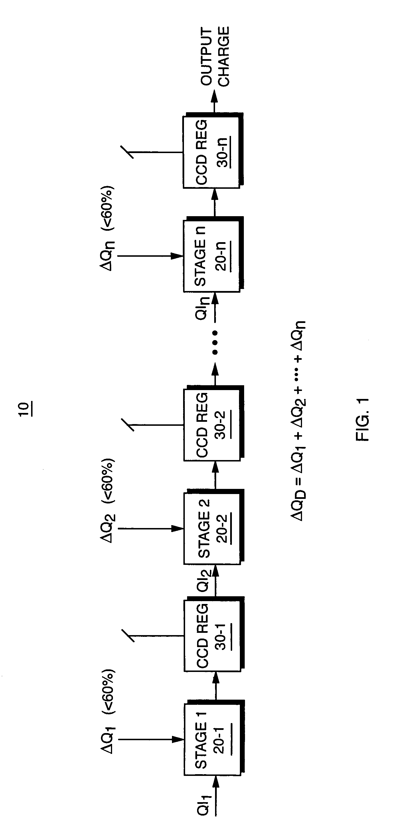
[0011]In one preferred embodiment, the subtraction is pipelined using at least two stages. However, extension to more that two stages is straightforward and is typically utilized in designs requiring high frequency operation, or if subtraction of relatively large fractions of the input charge (e.g., >90% of the input amount) are required.

Problems solved by technology

This is a highly undesirable result in a circuit which is expected to subtract a very precise amount of charge on successive clock cycles at high operating frequency.

Method used


Image

  • Device for subtracting or adding a constant amount of charge in a charge-coupled device at high operating frequencies
  • Device for subtracting or adding a constant amount of charge in a charge-coupled device at high operating frequencies
  • Device for subtracting or adding a constant amount of charge in a charge-coupled device at high operating frequencies

Examples


Embodiment Construction

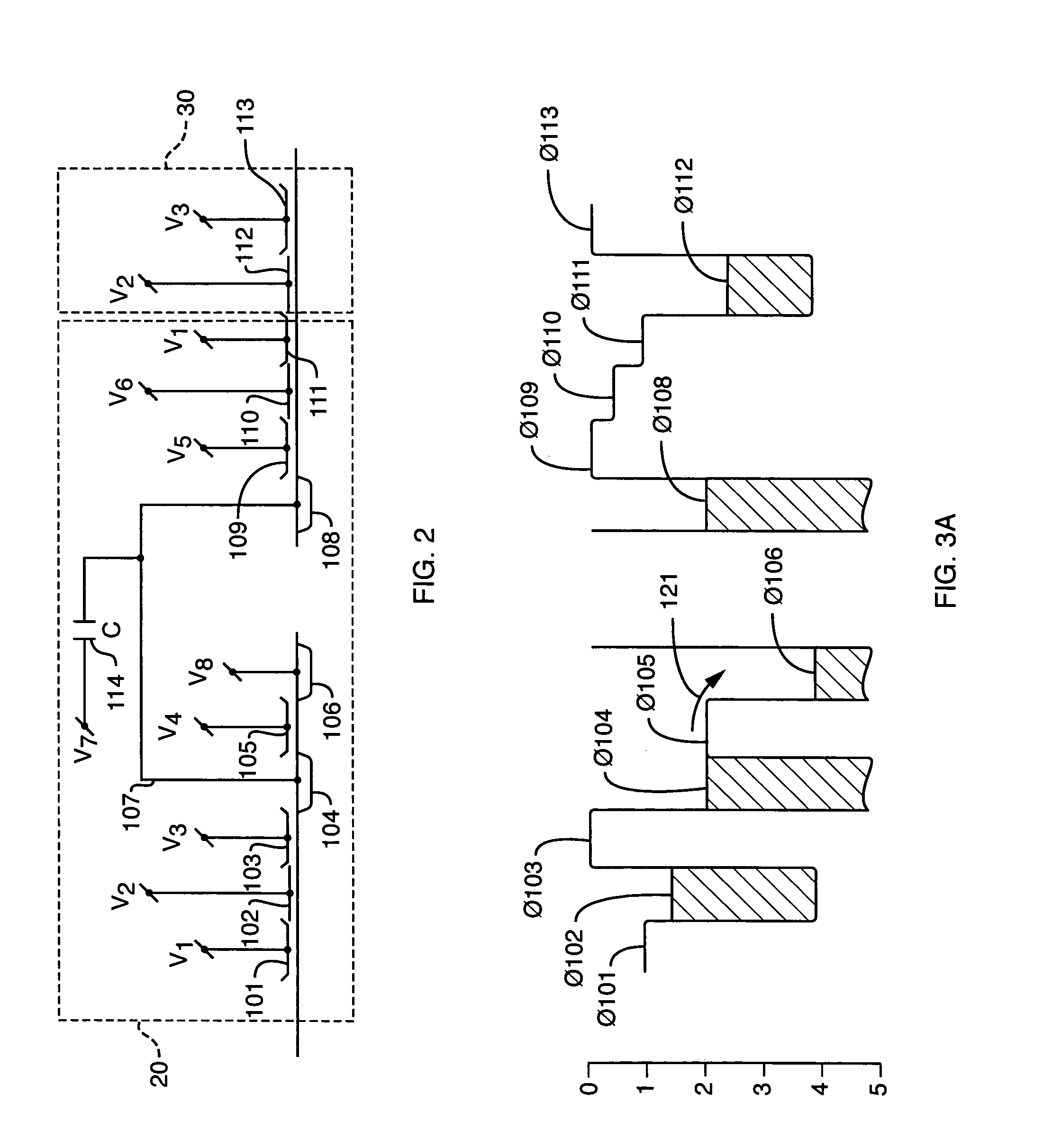
[0019]The present invention is a circuit that is capable of being configured to subtract a precise amount of charge from a given charge sample in a Charge Coupled Device (CCD). A key feature of the invention is the ability to subtract an amount of charge from any value of input charge sampled at high operating frequencies, even when the amount of charge to be subtracted makes up a very large fraction (greater than 90%) of the input charge sample. Unlike prior art approaches to charge subtraction, the present invention does not suffer from a memory effect on the value of charges subtracted. The subtraction operation is split into two or more stages, with each stage removing only a portion of total charge to be removed. The subtraction stages together combine to remove the total desired value of charge. In a preferred embodiment, each successive subtraction stage removes a correspondingly lesser amount of charge. The invention not only provides for greater accuracy in the amount of ch...


PUM


Abstract

A circuit for adding or subtracting an amount of charge from a charge sample, such as in a Charge Coupled Device (CCD), by portioning and pipelining the processing stages, to avoid introducing a memory effect. The operation, such as subtraction, is split into multiple stages, with each stage responsible for removing only a portion of the total amount of charge that is desired to be removed. The subtraction pipeline stages operate together to remove the total desired charge amount. In one embodiment each successive subtraction stage removes a corresponding lesser amount of charge. As a result, greater accuracy in the amount of charge removed is achieved as well operation at higher frequencies than previous charge subtraction approaches.

Description

BACKGROUND OF THE INVENTION[0001]This invention relates to a circuit for subtracting a constant amount of charge from a given charge sample such as may be used in a Charge Coupled Device (CCD).[0002]Charge Coupled Devices (CCDs) now find widespread use in consumer devices, including digital cameras, cellular telephones, wireless data network equipment, audio devices such as MP3 players, and video equipment such as Digital Video Disk (DVD) players, High Definition Digital Television (HDTV) equipment, and numerous other products. In CCD-based circuits, signals are represented as charge packets or as differential charge packet-pairs.[0003]The CCD devices themselves provide a basic function of storing and moving isolated packets of charge. Various circuits are known in the art for then performing arithmetic and other operations on the stored packets. For example, charge packets can be added together (merged), split into two or more pieces, conditionally steered down one circuit path or ...

Claims


Application Information

Patent Timeline
Patent Type & Authority Patents(United States)
IPC IPC(8): G11C19/28H03K23/46H01L27/148
CPCG11C19/282H01L27/14806G11C19/287G11C19/28G11C19/36
Inventor KUSHNER, LAWRENCE J.ANTHONY, MICHAEL P.KOHLER, EDWARD
Owner KENET
Learn More