Method for programming and erasing non-volatile memory with nitride tunneling layer

a technology of nitride tunneling and non-volatile memory, which is applied in the direction of digital storage, semiconductor devices, instruments, etc., can solve the problems of low efficiency of hot carrier (electron or electron hole) injection through the tunnel oxide layer, and achieve the effect of promoting the efficiency of a programming operation or an erasing operation of a memory devi

Inactive Publication Date: 2006-02-21
MACRONIX INT CO LTD
View PDF4 Cites 0 Cited by
  • Summary
  • Abstract
  • Description
  • Claims
  • Application Information

AI Technical Summary

Benefits of technology

[0009]Accordingly, this invention provides a method for programming and erasing a non-volatile memory with a nitride tunneling layer, which can promote the efficiency of a programming operation or an erasing operation of a memory device.
[0013]Since the tunneling layer in this invention is made from silicon nitride that has a energy barrier lower than that of silicon oxide used in the prior art, the efficiency of the channel hot carrier injection can be promoted and the operating rates of the memory device are thus increased.
[0014]Besides, since the dielectric constant of silicon nitride is higher than that of silicon oxide, lower operating voltages can be used to program or to erase the non-volatile memory with a nitride tunneling layer. Therefore, the critical dimension and the size of a memory cell can be further reduced for a higher integration.

Problems solved by technology

However, since the SONOS memory and the NROM both use silicon oxide as the material of the tunneling layer, the following problems are encountered.
Since silicon oxide has a high energy barrier for an electron and an electron hole, the efficiency of hot carrier (electron or electron hole) injection through the tunnel oxide layer is low when the channel hot carrier injection mechanism is used to program or to erase the SONOS or NROM device.

Method used


Image

  • Method for programming and erasing non-volatile memory with nitride tunneling layer
  • Method for programming and erasing non-volatile memory with nitride tunneling layer
  • Method for programming and erasing non-volatile memory with nitride tunneling layer

Examples


Embodiment Construction

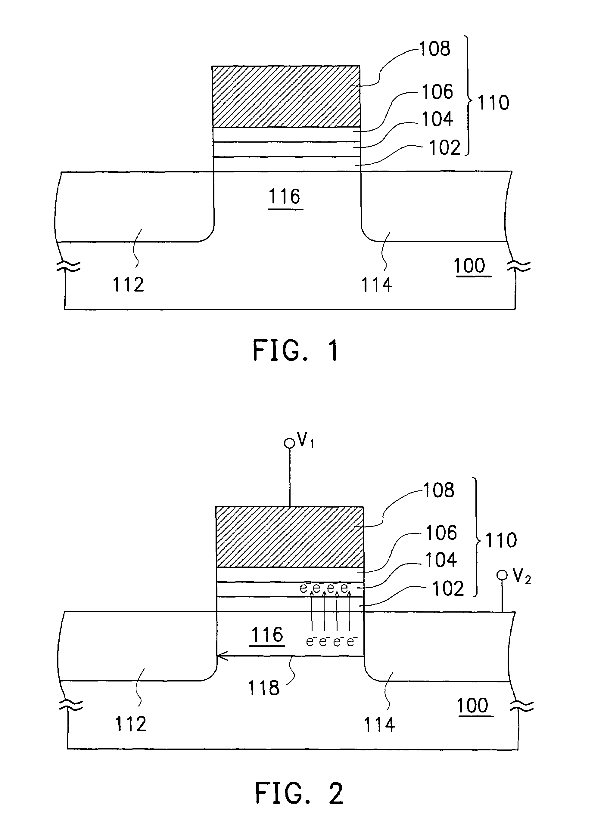
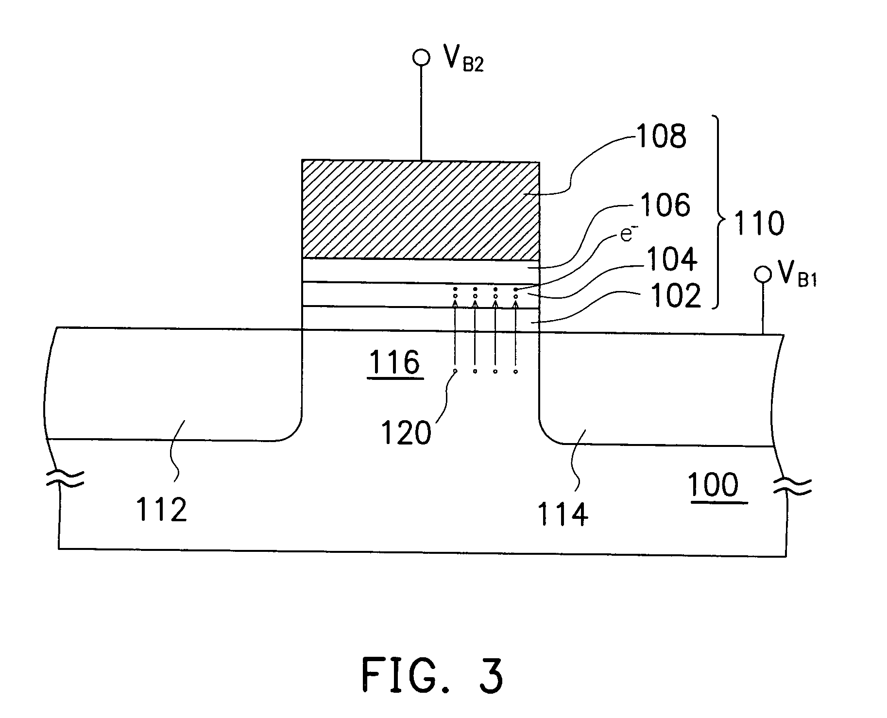
[0020]FIG. 1 schematically illustrates a non-volatile memory with a nitride tunneling layer according to a preferred embodiment of this invention in a cross-sectional view.

[0021]Refer to FIG. 1, the non-volatile memory with a nitride tunneling layer comprises a substrate 100, a nitride tunneling layer 102, a charge-trapping layer 104, a dielectric layer 106, a gate conductive layer 108, a source region 112, a drain region 114, and a channel region 116.

[0022]The substrate 100 comprises, for example, silicon. The substrate 100 is of n-type (p-type) when the non-volatile memory to be formed is a p-channel (n-channel) memory.

[0023]The nitride tunneling layer 102 is disposed on the substrate 100. The nitride tunneling layer 102 is formed by, for example, chemical vapor deposition (CVD).

[0024]The charge-trapping layer 104 is disposed on the nitride tunneling layer 102. The material of the charge-trapping layer 104a is, for example, silicon nitride and the method for forming the charge-tra...


PUM


Abstract

A method for programming and erasing a non-volatile memory with a nitride tunneling layer is described. The non-volatile memory is programmed by applying a first voltage to the gate and grounding the substrate to turn on a channel between the source and the drain, and applying a second voltage to the drain and grounding the source to induce a current in the channel and thereby to generate hot electrons therein. The hot electrons are injected into a charge-trapping layer of the non-volatile and trapped therein through the nitride tunneling layer. The non-volatile memory is erased by applying a first positive bias to the drain, applying a second positive bias to the gate, and grounding the source and the substrate to generate hot electron holes in the channel region. The hot electron holes are injected into the charge-trapping layer through the nitride tunneling layer.

Description

CROSS-REFERENCE TO RELATED APPLICATION[0001]This application is a divisional application of, and claims the priority benefit of, U.S. application Ser. No. 10 / 015,414 filed on Dec. 12, 2001.BACKGROUND OF THE INVENTION[0002]1. Field of Invention[0003]The present invention relates to a method for programming and erasing a non-volatile memory. More particularly, the present invention relates to a method for programming and erasing a non-volatile memory with a nitride tunneling layer.[0004]2. Description of Related Art[0005]The family of the non-volatile memory includes the erasable programmable read-only memory (EPROM) and the electrically erasable programmable read-only memory (E2PROM). Particularly, the E2PROM can be erased and programmed electrically and is capable of retaining data even if the power is turned off, and therefore is widely used in personal computers and in electronic apparatuses.[0006]The E2PROM with a silicon oxide / silicon nitride / silicon oxide (ONO) stacked structur...

Claims


Application Information

Patent Timeline
Patent Type & Authority Patents(United States)
IPC IPC(8): G11C16/04G06F12/00G11C5/06G11C16/10G11C16/14
CPCG11C16/0466G11C16/14G11C16/10
Inventor FAN, TSO-HUNGYEH, YEN-HUNGCHAN, KWANG-YANGLIU, MU-YILU, TAO-CHENG
Owner MACRONIX INT CO LTD
Why Eureka
Try Eureka