Apparatus for beam deflection

Active Publication Date: 2006-02-21
LEICA MICROSYSTEMS CMS GMBH
View PDF5 Cites 3 Cited by
  • Summary
  • Abstract
  • Description
  • Claims
  • Application Information

AI Technical Summary

Benefits of technology

[0006]It is therefore the object of the present invention to describe an apparatus for beam deflection that allows maximum variability in terms of frequency range and maximum attainable oscillation frequency, so as thereby to create flexible and versatile utilization capabilities. The apparatus is moreover intended to be able to establish essentially any desired angular offset from the zero point position.
[0008]It is a further the object of the present invention to describe scanning microscope which allows maximum variability in terms of frequency range and maximum attainable oscillation frequency, so as thereby to create flexible and versatile utilization capabilities. The scanning microscope is moreover intended to be able to establish essentially any desired angular offset from the zero point position.
[0010]What has been recognized according to the present invention is firstly that resonant galvanometers are typically of high mechanical quality. In the context of an alternating rotation of a resonant galvanometer at oscillation frequencies that are far below the resonant frequency, this makes possible a direct transfer, without dephasing, to a mirror that is, for example, attached to the resonant galvanometer.
[0011]A rotary drive that comprises two mutually independent drive units combines the characteristic properties of the two drive units. The advantage of variable and flexible utilization of the apparatus according to the present invention outweighs the disadvantage of the need for two drive units per rotation axis.
[0026]To minimize distortion errors, one of the two mirrors could be arranged as a paddle scanner. In particular, the mirror arranged first in the illumination beam path could be embodied as a paddle scanner. This achieves, approximately, rotation of the beam about a virtual rotation point, which advantageously makes possible the use of small mirror surfaces. In addition, distortion errors that are induced by beam deflection can be greatly minimized.

Problems solved by technology

In addition, in some circumstances it is possible for undesirable oscillation-frequency-related deviations in the activation signal of a galvanometer (reference position) with respect to the actually established angular or rotational position of the mirror (actual position) to occur.
Resonant galvanometers can be operated only at the corresponding resonant frequency, however, so that versatile utilization is not possible.
In addition, it is not possible with resonant galvanometers to establish an angular offset from the zero point position.

Method used


Image

  • Apparatus for beam deflection
  • Apparatus for beam deflection
  • Apparatus for beam deflection

Examples


Embodiment Construction

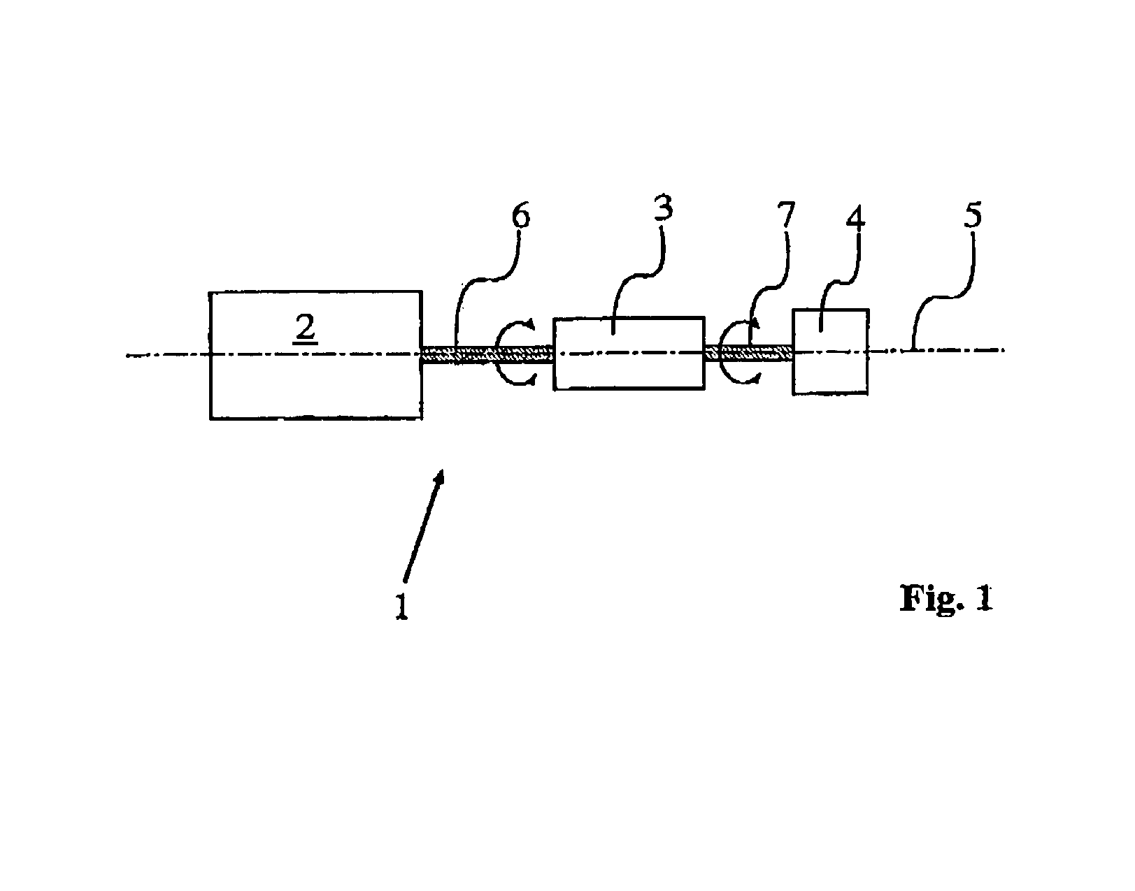
[0030]FIG. 1 shows an apparatus for beam deflection for confocal laser scanning microscopy, in which rotary drive 1 comprises two mutually independent drive units 2, 3. The two drive units (2, 3) are embodied as galvanometers and / or as stepping motors and rotate mirror 4, together or mutually independently, about a rotation axis 5. The rotation axes of the two drive units 2, 3 are identical, and are drawn with a dot-dash line labeled 5 in FIG. 1.

[0031]Second drive unit 3 is mounted on shaft 6 of first drive unit 2. Second drive unit 3 can be rotated by first drive unit 2. Mirror 4 is mounted on shaft 7 of second drive unit 3. Drive unit 3 is embodied as a resonant galvanometer with which a fast beam deflection is accomplished. The arrangement ensures, in particular, that shaft 6 of galvanometer 2 is held nonrotatably when resonant galvanometer 3 is in operation.

[0032]A slow beam deflection is performed with galvanometer 2, the arrangement ensuring that shaft 7 of resonant galvanomet...


PUM


Abstract

The invention concerns an apparatus for beam deflection, in particular for scanning microscopy, a light beam being deflectable by a mirror arrangement that is alternatingly rotatable by a rotary drive. The apparatus for beam deflection makes possible maximum variability in terms of frequency range and maximally achievable oscillation frequency, and is thus usable in flexible and versatile fashion. It moreover allows almost any desired angular offset from the zero point position to be established, and is characterized in that the rotary drive comprises two mutually independent drive units which rotate the mirror arrangement, together or mutually independently, about a rotation axis.

Description

CROSS REFERENCE TO RELATED APPLICATIONS[0001]This invention claims priority of a German patent application DE 199 56 439.6 which is incorporated by reference herein.BACKGROUND OF INVENTION[0002]The present invention concerns an apparatus for beam deflection, in particular for scanning microscopy, the light being deflectable by a first mirror arrangement that is alternatingly rotatable by a rotary drive. Apparatuses of the generic type are used in particular in scanning microscopy, in particular in confocal laser scanning microscopy. Merely by way of example, reference is made to DE 43 22 694 A1, in which a light beam is deflected with the aid of at least three mirrors, each having its own rotary drive.[0003]DE 196 54 210 A1 discloses, per se, an optical arrangement for scanning a beam in two axes lying substantially perpendicular to one another, said arrangement having two rotationally driven mirrors, one of the two mirrors having a further mirror nonrotatably associated with it in ...

Claims


Application Information

Patent Timeline
IPC IPC(8): G02B26/08G02B21/00G02B26/10
CPCG02B21/0048
Inventor STORZ, RAFAELENGELHARDT, JOHANNBIRK, HOLGERBRADL, JOACHIM
Owner LEICA MICROSYSTEMS CMS GMBH
Why Eureka
Try Eureka