Switching power supply control circuit and switching power supply using same
- Summary
- Abstract
- Description
- Claims
- Application Information
AI Technical Summary
Benefits of technology
Problems solved by technology
Method used
Image
Examples
Embodiment Construction
[0026]Here follows a detailed description of a preferred embodiment of the present invention made with reference to the appended drawings.
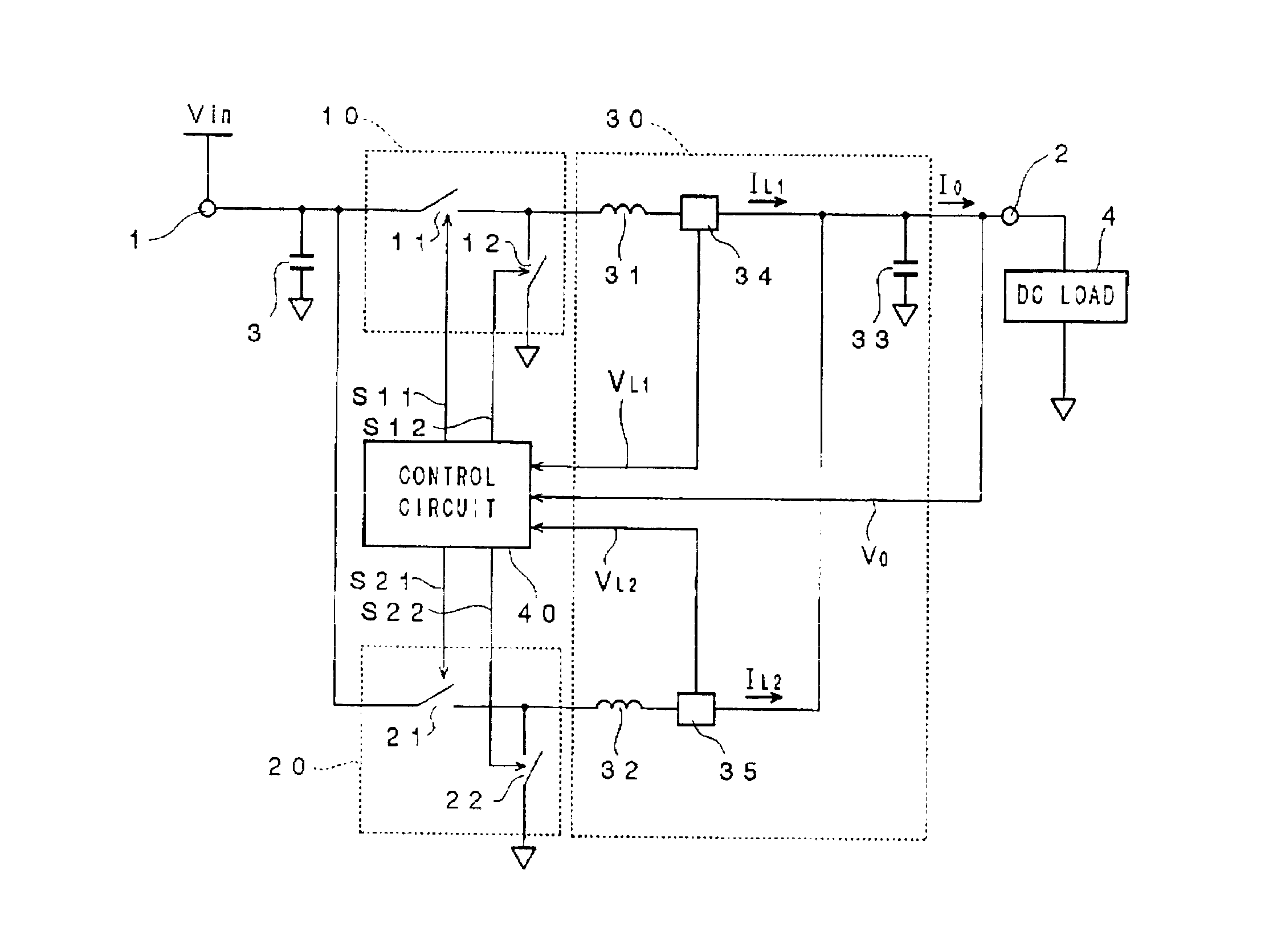
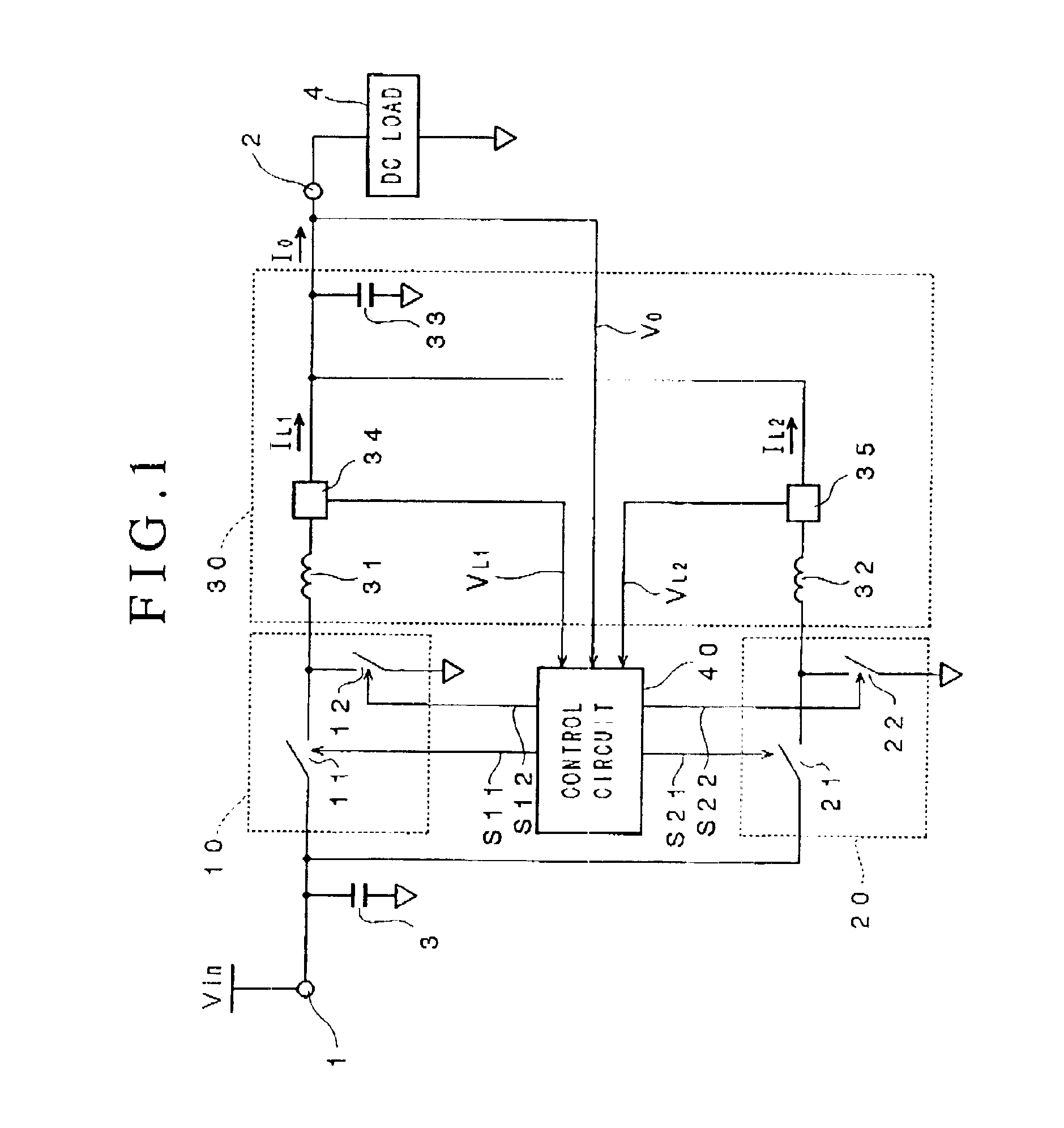
[0027]FIG. 1 is a circuit diagram of the switching power supply according to a preferred embodiment of the present invention.
[0028]As shown in FIG. 1, the switching power supply according to this embodiment is a unit that steps down the DC input voltage Vin supplied to input power terminal 1 and generates the DC output voltage Vn which is supplied to output power terminal 2, consisting of switching circuit blocks 10 and 20, control circuit block 30 and control circuit 40. To wit, the switching power supply according to this embodiment is a switching power supply based on the parallel operation scheme, and a CPU or other DC load 4 that requires a large current is connected to the output power terminal 2.
[0029]The switching circuit block 10 has switch elements 11 and 12, while the output circuit block 20 has switch elements 21 and 22. Switch element...
PUM
 Abstract
Description
Claims
Application Information
 - R&D Engineer
- R&D Manager
- IP Professional
- Industry Leading Data Capabilities
- Powerful AI technology
- Patent DNA Extraction
Browse by: Latest US Patents, China's latest patents, Technical Efficacy Thesaurus, Application Domain, Technology Topic, Popular Technical Reports.
© 2024 PatSnap. All rights reserved.Legal|Privacy policy|Modern Slavery Act Transparency Statement|Sitemap|About US| Contact US: help@patsnap.com


