Laser diode driving circuit with safety feature

a technology of safety features and driving circuits, applied in semiconductor lasers, optical radiation measurement, instruments, etc., can solve the problems of unsafe laser power levels, relatively complex design of current comparators, and prior art drive circuits without safety features

Active Publication Date: 2006-02-21
LUMENTUM OPERATIONS LLC
View PDF6 Cites 13 Cited by
  • Summary
  • Abstract
  • Description
  • Claims
  • Application Information

AI Technical Summary

Benefits of technology

[0025]a variable current source coupled to an output of said operational amplifier, and coupled to said laser diode for biasing said laser diode; whereby the operational amplifier adjusts the output signal thereof to ensure that the set voltage and the main reference voltage ar...

Problems solved by technology

Unfortunately, the design of current comparators can be relatively complicated.
Moreover, the prior art drive circuits do not include safety features to protect against unsafe levels ...

Method used


Image

  • Laser diode driving circuit with safety feature
  • Laser diode driving circuit with safety feature
  • Laser diode driving circuit with safety feature

Examples


Embodiment Construction

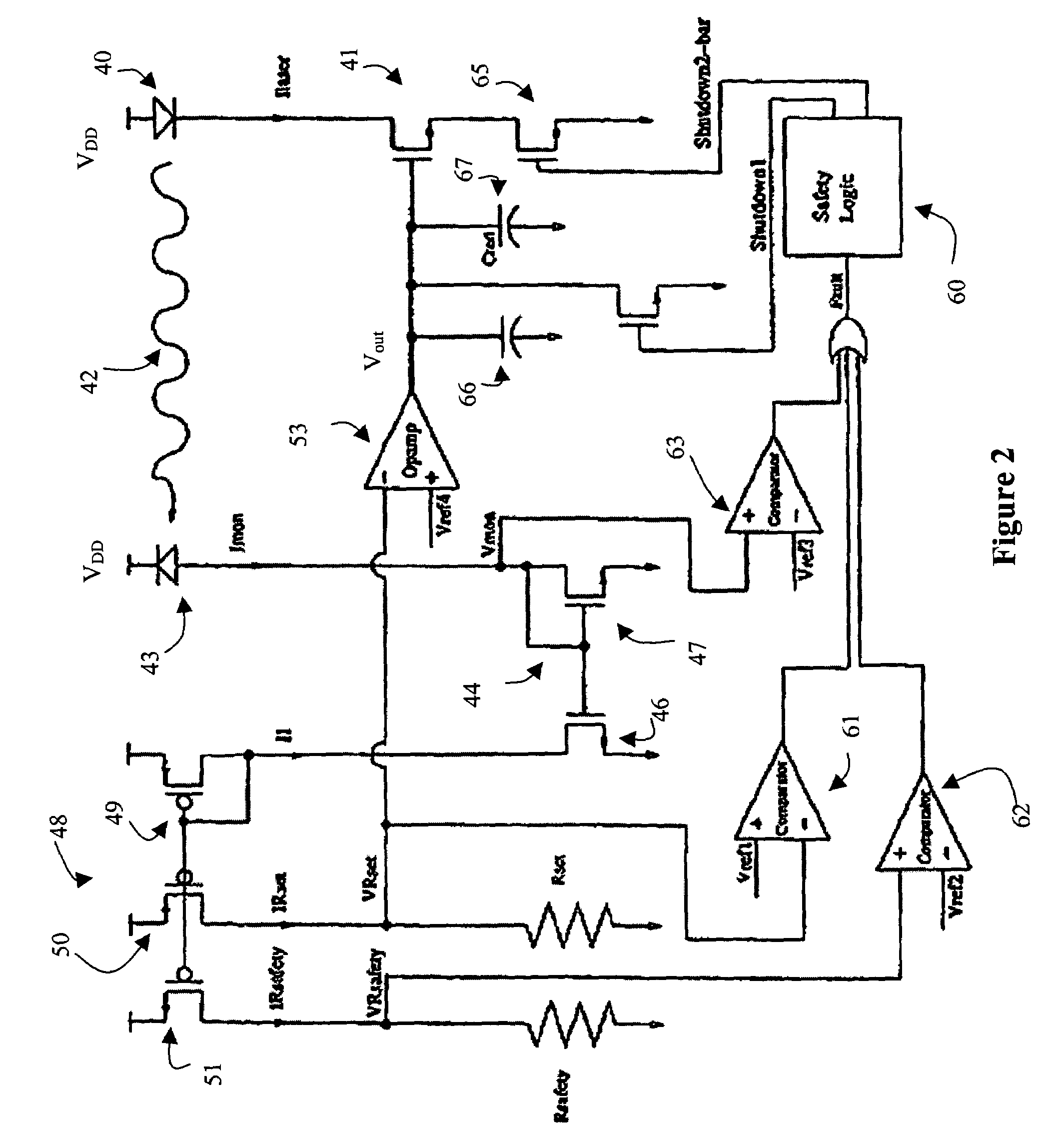
[0033]With reference to FIG. 2, a laser diode 40 is coupled to a voltage source VDD and a current source 41, in the form of a NFET. For the purposes of a feedback loop, a portion 42 of the light launched from the laser diode 40 is directed at a monitor diode 43, which generates a monitor current Imon proportional to the optical power produced by the laser diode 40. The monitor current Imon is fed to a first current mirror 44, which produces a mirror current I1 substantially equal to Imon. The current mirror 44, which has a low impedance, is provided to ensure that the monitor diode node is a non-dominant pole in the feedback loop. The first current mirror 44 is comprised of two transistors 46 and 47, with their gates electrically coupled together. The mirror current I1 is fed to a second current mirror 48, which produces safety current IRsafety and set current IRset. The second current mirror 48 is comprised of three transistors 49, 50 and 51, with their gates electrically coupled t...


PUM


Abstract

The invention relates to a feedback loop for a laser diode driving circuit for ensuring that the laser diode generates optical power at a constant safe level. The feedback loop includes a monitor diode, which generates a monitor current Imon, and a set resistance for generating a set voltage based on the monitor current and the set resistance. The set voltage is compared with a reference voltage in an operational amplifier, which generates a control signal for controlling the laser diode current source. The laser diode current source dictates the amount of bias current transmitted to the laser diode. Safety features, in the form of voltage comparators, are provided to ensure that: a) the feedback loop is closed, i.e. Imon is not too low; b) the optical power is not above standard safety threshold, i.e. Imon is not too high; and c) the monitor diode voltage is sufficient to provide specified optical power to electrical power conversion.

Description

CROSS-REFERENCE TO RELATED APPLICATIONS[0001]The present invention claims priority from U.S. patent application Ser. No. 60 / 403,368 filed Aug. 15, 2002.TECHNICAL FIELD[0002]The present invention relates to a laser diode driving circuit, and in particular to a laser diode drive circuit utilizing voltage comparators for setting the laser power and providing safety features.BACKGROUND OF THE INVENTION[0003]Conventional laser diode drive circuits, such as the one disclosed in U.S. Pat. No. 6,392,215 issued May 21, 2002 in the name of Baumgartner et al and illustrated in FIG. 1, utilize a feedback loop 10 to control the bias current Ilaser, which drives the laser diode 12. The feedback loop 10 includes a monitor diode 16, which produces a monitor current Imon proportional to the power output of the laser diode 12. The monitor current Imon is mirrored via current mirror 18, which is comprised of transistors 26 and 28, and compared to a predetermined reference current Iref, which is genera...

Claims


Application Information

Patent Timeline
IPC IPC(8): G01J1/32G01J1/42H01S5/068
CPCG01J1/4257H01S5/06825
Inventor HEDIN, DANIEL SCOTTPASCHAL, MATTHEW JAMES
Owner LUMENTUM OPERATIONS LLC
Why Eureka
Try Eureka