
Transmission output power control device for use in a burst transmitter and control method

a control device and transmitter technology, applied in the direction of phase-modulated carrier systems, baseband system details, modulation, etc., can solve the problems of increasing power consumption, increasing processing and power consumption, and requiring an increase in power consumption, so as to reduce the amount of memory, the amount of processing, and the amount of power required

Inactive Publication Date: 2006-02-07
MITSUBISHI ELECTRIC CORP
View PDF7 Cites 9 Cited by
  • Summary
  • Abstract
  • Description
  • Claims
  • Application Information

AI Technical Summary

Benefits of technology

[0016]A first object of the present invention is, in a burst transmitter using a constant envelope modulation, to reduce the amount of memory, the amount of processing, and the consumption of power required for a ramp process to the transmission output power.
[0017]A second object of the invention is to perform the ramp process in such a way as to more effectively suppress the spreading of the spectrum of the transmission output power.
[0018]A third object of the invention is to reduce the amount of processing and the consumption of power and to suppress the spreading of the spectrum.

Problems solved by technology

Therefore, a large amount of data must be stored in the ramp amplitude waveform data memory 2016 and the control voltage signal D / A converter 2006 must be controlled each time a transmission is made, which requires an increased amount of processing and increased consumption of power.
Hence the modulation systems require their respective ramp amplitude waveform data memories and their respective operation procedures, which also requires increased consumption of power.

Method used


Image

  • Transmission output power control device for use in a burst transmitter and control method
  • Transmission output power control device for use in a burst transmitter and control method
  • Transmission output power control device for use in a burst transmitter and control method

Examples


Embodiment Construction

[0055]The preferred embodiments of the present invention are now described referring to the accompanying drawings.

[0056]First Preferred Embodiment

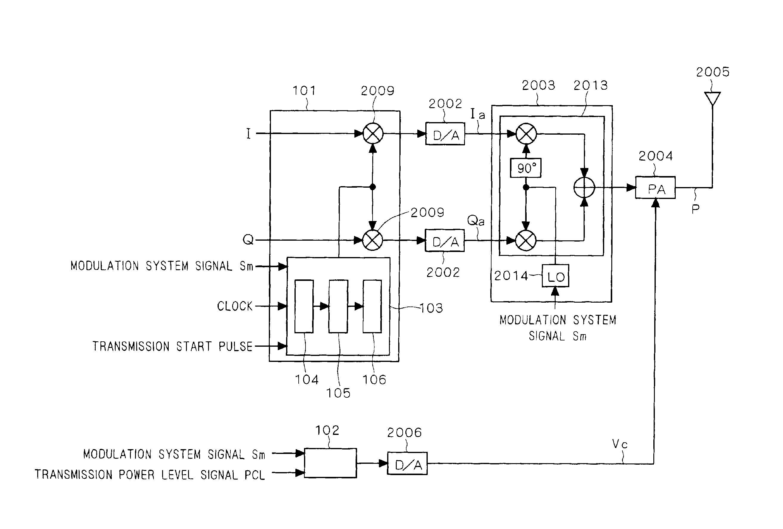
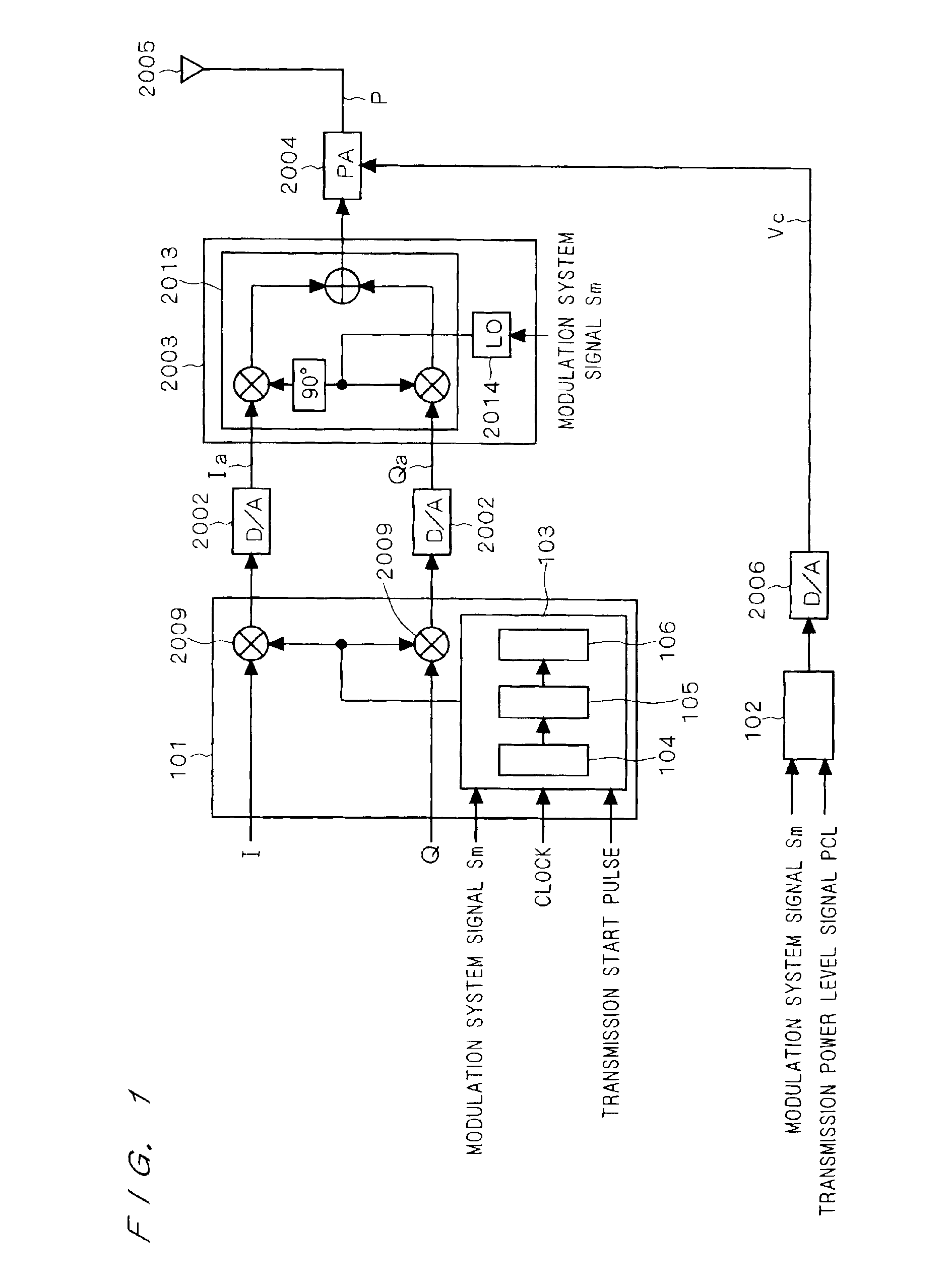
[0057]FIG. 1 is a block diagram that shows a dual-mode burst transmitter according to a first preferred embodiment; the dual-mode burst transmitter uses an amplitude modulation system and a constant envelope modulation system (e.g. the PDC system and the GSM system). In FIG. 1, the baseband signal D / A converters 2002, the modulating unit 2003, the power amplifier 2004, the antenna 2005, the control voltage signal D / A converter 2006, and the multiplication mixers 2009 are the same as those described in Background Art. The reference numeral 101 shows an I / Q signal amplitude control unit which includes a waveform data generating portion 103 and the multiplication mixers 2009, where the waveform data generating portion 103 includes a counter 104, a table reference number generating portion 105, and a ramp amplitude waveform data memory 106. Th...


PUM


Abstract

A burst transmitter is obtained which, when a constant envelope modulation is used, can control the envelope of a transmission output power by controlling a baseband signal without causing the spreading of the spectrum. A transmission output power control device includes: an I / Q signal amplitude control unit (101) for variably controlling the shape of a rise and a fall of the waveform of a baseband signal and its burst transmission time from the end of the rise to the beginning of the fall in accordance with a modulation system signal; a modulating unit (2003) for modulating the baseband signal controlled in the I / Q signal amplitude control unit (101) into a high-frequency signal for transmission in accordance with the modulation system signal; an amplifier (2004) for amplifying the transmission high-frequency signal modulated in the modulating unit (2003); and a control voltage signal selecting unit (102) for outputting a predetermined constant voltage which is determined by the modulation system signal and a transmission power level signal, so as to control the output power of the amplifier.

Description

BACKGROUND OF THE INVENTION[0001]1. Field of the Invention[0002]The present invention relates to a transmission output power control device and a transmission output power control method for use in a burst transmitter.[0003]2. Description of the Background Art[0004]Considering the recent increase in the number of users of cellular phone terminals, it is desirable to make as high as possible the efficiency of use of the frequency bands in the cellular phone system etc. In a burst transmitter used in the cellular phone terminal, in order to efficiently utilize the frequency band, the output power for transmission is ramped so that it rises and falls slowly, thereby preventing the spectrum from spreading in a wide range. The cellular phone system complexly uses a plurality of radio systems which use different communication systems, and the different systems use different types of modulation. Thus the cellular phone terminals include so-called dual-mode terminals which have two modulati...

Claims


Application Information

Patent Timeline
IPC IPC(8): H04B1/04H03G3/30H04L27/36H04L27/20
CPCH03G3/3047
Inventor HIGUCHI, KOJI
Owner MITSUBISHI ELECTRIC CORP
Learn More